management
1084 TopicsHow I did it - "F5 BIG-IP Observability with Dynatrace and F5 Telemetry Streaming"
Welcome back to another edition of “How I Did It.” It’s been a while since we looked at observability… Oh wait, I just said that. Anyway, in this post I’ll walk through how I integrated F5 Telemetry Streaming with Dynatrace. To show the results, I’ve included sample dashboards that highlight how the ingested telemetry data can be visualized effectively. Let’s dive in before I repeat myself again.262Views4likes0CommentsCertificate Automation for BIG-IP using CyberArk Certificate Manager, Self-Hosted
The issue of reduced lifetimes of TLS certificates is top of mind today. This topic touches upon reducing the risks associated with human day-to-day management tasks for such critical components of secure enterprise communications. Allowing a TLS certificate to expire, by simple operator error often, can preclude the bulk of human or automated transactions from ever completing. In the context of e-commerce, as only one single example, such an outage could be financially devastating. Questions abound: why are certificate lifetimes being lowered; how imminent is this change; will it affect all certificates? An industry association composed of interested parties, including many certificate authority (CA) operators, is the CA/Browser Forum. In a 29-0 vote in 2025, it was agreed public TLS certificates should rapidly evolve from the current 398 day de-facto lifetime standard to a phased arrival at a 47 day limit by March 2029. An ancillary requirement, demonstrating the domain is properly owned, known as Domain Control Validation (DCV) will drop to ten days. Although the governance of certificate lifecycles overtly pertains to public certificates, the reality is enterprise-managed, so called private CAs, likely need to fall in lock step with these requirements. Pervasive client-side software elements, such as Google Chrome, are used transparently by users with certificates that may be public or enterprise issued, and having a single set of criteria for accepting or rejecting a certificate is reasonable. Why Automated Certificate Management on BIG-IP, Now More than Ever? A principal driver for shortening certificate (cert) lifetimes; the first phase will reduce public certs to 200-day durations this coming March 15, 2026, is simply to lessen the exposure window should the cert be compromised and mis-used by an adversary. Certificates, and their corresponding private keys, can be manually maintained using human-touch. The BIG-IP TMUI interface has a click-ops path for tying certificates and keys to SSL profiles, for virtual servers that project HTTPS web sites and services to consumers. However, this requires something valuable, head count, and diligence to ensure a certificate is refreshed, perhaps through an enterprise CA solution like Microsoft Certificate Authority. It is critical this is done, always and without fail, well in advance of expiry. An automated solution that can take a “set it and forget it” approach to maintain both initial certificate deployment and the critical task of timely renewals is now more beneficial than ever. Lab Testing to Validate BIG-IP with CyberArk Trusted Protection Platform (TPP) A test bed was created that involved, at first, a BIG-IP in front of an HTTP/HTTPS server fleet, a Windows 2019 domain controller and a Windows 10 client to test BIG-IP virtual servers with. Microsoft Certificate Authority was installed on the server to allow for the issuance of enterprise certs for any of the HTTPS virtual servers created on the BIG-IP. Here is the lab layout, where virtual machines were leveraged to create the elements, including BIG-IP virtual edition (VE). The lab is straight forward; upon the Windows 2019 domain controller the Microsoft Certificate Authority component was installed. Microsoft SQL server 2019 was also installed, along with SQL Management Studio. In an enterprise production environment, these components would likely never share the domain controller host platform but are fine for this lab setup. Without an offering to shield the complexity and various manual processes of key and cert management, an operator will need to be well-versed with an enterprise CA solution like Microsoft’s. A typical launching sequence from Server Manager is shown below, with the sample lab CA and a representative list of issued certificates with various end dates. Unequipped with a solution like that from CyberArk, a typical workflow might be to install the web interface, in addition to the Microsoft CA and generate web server certificates for each virtual server (also frequently called “each application”) configured on the BIG-IP. A frequent approach is to create a unique web server template in Microsoft CA, with all certificates generated manually following the fixed, user specified certificate lifetime. As seen below, we are not installing anything but the core server role of Certificate Authority, the web interface for requesting certificates is not required and is not installed as a role. CyberArk Certificate Manager, Self-Hosted – Three High-Value Use Cases The self-hosted certificate and key management solution from CyberArk is a mature, tested offering having gained a significant user base and still may be known by previous names such as Venafi TLS Protect, or Venafi Trust Protection Platform (TPP). CyberArk acquired Venafi in 2024. Three objectives were sought in the course of the succinct proof-of-concept lab exercise that represented expected use cases: 1. Discover all existing BIG-IP virtual server TLS certificates 2. Renew certificates and change self-signed instances to enterprise PKI-issued certificates 3. Create completely new certificates and private keys and assign to BIG-IP new virtual servers The following diagram reflects the addition of CyberArk Certificate Manager, or Venafi TPP if you have long-term experience with the solution, to the Windows Server 2019 instance. Use Case One – Discover all BIG-IP Existing Certificates Already Deployed In our lab solution, to re-iterate the pivotal role of CyberArk Certificate Manager (Venafi TPP) in certificate issuance, we have created a “PolicyTree” policy called “TestingCertificates”. This will be where we will discover all of our BIG-IP virtual servers and their corresponding SSL Client and SSL server profiles. An SSL Client profile, for example, dictates how TLS will behave when a client first attempts a secure connection, including the certificate, potentially a certificate chain if signage was performed with an intermediate CA, and protocol specific features like support for TLS 1.3 and PQC NIST FIPS 203 support. Here are the original contents of the TestingCertificates folder, before running an updated discovery, notice how both F5 virtual servers (VS) are listed and the certificates used by a given VS. This is an example of the traditional CyberArk GUI look and feel. A simple workflow exists within the CyberArk platform to visually set up a virtual server and certificate discovery job, it can be run manually once, when needed, or set to operate on a regular schedule. This screenshot shows the fields required for the discovery job, and also provides an example of the evolved, streamlined approach to the user interface, referred to as the newer “Aperture” style view. Besides the enormous time savings of the first-time discovery of BIG-IP virtual servers, and certificates and keys they use in the form of SSL profiles, we can also look for new applications stood up on the BIG-IP through on-going CyberArk discovery runs. In the above example, we see a new web service implemented at the FQDN of www.twotitans.com has just been discovered. Clicking the certificate, one thing to note is the certificate is self-signed. In real enterprise environments, there may be a need to re-issue such a certificate with the enterprise CA, as part of a solid security posture. Another, even more impactful use case is when all enterprise certificates need to be easily and quickly switched from a legacy CA to a new CA the enterprise wants to move to quickly and painlessly. We see with one click on a certificate discovered that some key information is imparted. On this one screen, an operator might note that this particular certificate may warrant some improvements. It is seen that only 2048 bits are used in the certificate; the key is not making use of advanced storage and on, such as a NetHSM, and the certificate itself has not been built to support revocation mechanisms such as Content Revocation Lists (CRLs) or Online Certificate Status Protocol (OCSP). Use Case Two - Renew Certificates and Change Self-signed Instance to Enterprise PKI-Issued Certificates The automated approach of a solution like CyberArk’s likely means manual interactive certificate renewal is not going to be prevalent. However, for the purpose of our demonstration, we can examine a current certificate, alive and active on a BIG-IP supporting the application, s3.example.com. This is the “before” situation (double-click image for higher resolution). The result upon clicking the “Renew Now” button is a new policy-specific updated 12-month lifetime will be applied to a newly minted certificate. As seen in the following diagram, the certificate and its corresponding private key are automatically installed on the SSL Client Profile on the BIG-IP that houses the certificate. The s3.example.com application seamlessly continues to operate, albeit with a refreshed certificate. A tactical usage of this automatic certificate renewal and touchless installation is grabbing any virtual servers running with self-signed certificates and updating these certificates to be signed by the enterprise PKI CA or intermediate CA. Another toolkit feature now available is to switch out the entire enterprise PKI from one CA to another CA, quickly. In our lab setup, we have a Microsoft CA configured; it is named “vlab-SERVERDC1-ca”. The following certificate, ingested through discovery by CyberArk from the BIG-IP, is self-signed. Such certificates can be created directly within the BIG-IP TMUI GUI, although frequently they are quickly generated with the OpenSSL utility. Being self-signed, traffic through into this virtual will typically cause browser security risk pop-ups. They may be clicked through by users in many cases, or the certificate may even be downloaded from the browser and installed in the client’s certificate store to get around a perceived annoyance. This, however, can be troublesome in more locked-down enterprise environments where an Active Directory group policy object (GPO) can be pushed to domain clients, precluding any self-signed certificates being resolved with a few clicks around a pop-up. It is more secure and more robust to have authorized web services, vetted, and then incorporated into the enterprise PKI environment. This is the net result of using CyberArk Certificate Manager, coupled with something like the Microsoft enterprise CA, to re-issue the certificate (double-click). Use Case Three - Create Completely New Certificates and Private Keys and Assign to BIG-IP New Virtual Servers Through the CyberArk GUI, the workflows to create new certificates are intuitive. Per the following image, right-click on a policy and follow the “+Add” menu. We will add a server certificate and store it on the BIG-IP certificate and key list for future usage. A basic set of steps that were followed: Through the BIG-IP GUI, setup the application on the BIG-IP as per a normal configuration, including the origin pool, the client SSL profile, and a virtual server on port 443 that ties these elements together. Create, on CyberArk, the server certificate with the details congruent with the virtual server, such as common name, subject alternate name list, key length desired. On CyberArk, create a virtual server entry that binds the certificate just created to the values defined on the BIG-IP. The last step will look like this. Once the certificate is selected for “Renewal” the necessary elements will automatically be downloaded to the BIG-IP. As seen, the client’s SSL profile has now been updated with the new certificate and key signed by the enterprise CA. Summary This article demonstrated an approach to TLS certificate and key management for applications of all types, which harnesses the F5 BIG-IP for both secure and scalable delivery. With the rise in the number of applications that require TLS security, including advanced features enabled by BIG-IP, like TLS1.3 and PQC, coupled with the industry’s movement towards very short certificate lifecycle, the automation discussed will become indispensable to many organizations. The ability to both discover existing applications, switch out entire enterprise PKI offerings smoothly, and to agilely create new BIG-IP centered applications was touched upon.72Views3likes0Comments
Back to Basics: Health Monitors and Load Balancing
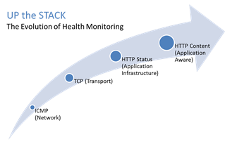
#webperf #ado Because every connection counts One of the truisms of architecting highly available systems is that you never, ever want to load balance a request to a system that is down. Therefore, some sort of health (status) monitoring is required. For applications, that means not just pinging the network interface or opening a TCP connection, it means querying the application and verifying that the response is valid. This, obviously, requires the application to respond. And respond often. Best practices suggest determining availability every 5 seconds or so. That means every X seconds the load balancing service is going to open up a connection to the application and make a request. Just like a user would do. That adds load to the application. It consumes network, transport, application and (possibly) database resources. Resources that cannot be used to service customers. While the impact on a single application may appear trivial, it's not. Remember, as load increases performance decreases. And no matter how trivial it may appear, health monitoring is adding load to what may be an already heavily loaded application. But Lori, you may be thinking, you expound on the importance of monitoring and visibility all the time! Are you saying we shouldn't be monitoring applications? Nope, not at all. Visibility is paramount, providing the actionable data necessary to enable highly dynamic, automated operations such as elasticity. Visibility through health-monitoring is a critical means of ensuring availability at both the local and global level. What we may need to do, however, is move from active to passive monitoring. PASSIVE MONITORING Passive monitoring, as the modifier suggests, is not an active process. The Load balancer does not open up connections nor query an application itself. Instead, it snoops on responses being returned to clients and from that infers the current status of the application. For example, if a request for content results in an HTTP error message, the load balancer can determine whether or not the application is available and capable of processing subsequent requests. If the load balancer is a BIG-IP, it can mark the service as "down" and invoke an active monitor to probe the application status as well as retrying the request to another available instance – insuring end-users do not see an error. Passive (inband) monitors are not binary. That is, they aren't simple "on" or "off" based on HTTP status codes. Such monitors can be configured to track the number of failures and evaluate failure rates against a configurable failure interval. When such thresholds are exceeded, the application can then be marked as "down". Passive monitors aren't restricted to availability status, either. They can also monitor for performance (response time). Failure to meet response time expectations results in a failure, and the application continues to be watched for subsequent failures. Passive monitors are, like most inline/inband technologies, transparent. They quietly monitor traffic and act upon that traffic without adding overhead to the process. Passive monitoring gives operations the visibility necessary to enable predictable performance and to meet or exceed user expectations with respect to uptime, without negatively impacting performance or capacity of the applications it is monitoring.3KViews1like2CommentsThe Limits of Cloud: Gratuitous ARP and Failover
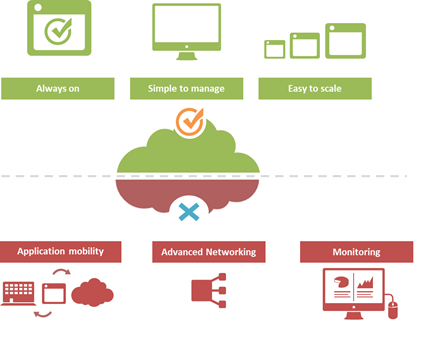
#Cloud is great at many things. At other things, not so much. Understanding the limitations of cloud will better enable a successful migration strategy. One of the truisms of technology is that takes a few years of adoption before folks really start figuring out what it excels at – and conversely what it doesn't. That's generally because early adoption is focused on lab-style experimentation that rarely extends beyond basic needs. It's when adoption reaches critical mass and folks start trying to use the technology to implement more advanced architectures that the "gotchas" start to be discovered. Cloud is no exception. A few of the things we've learned over the past years of adoption is that cloud is always on, it's simple to manage, and it makes applications and infrastructure services easy to scale. Some of the things we're learning now is that cloud isn't so great at supporting application mobility, monitoring of deployed services and at providing advanced networking capabilities. The reason that last part is so important is that a variety of enterprise-class capabilities we've come to rely upon are ultimately enabled by some of the advanced networking techniques cloud simply does not support. Take gratuitous ARP, for example. Most cloud providers do not allow or support this feature which ultimately means an inability to take advantage of higher-level functions traditionally taken for granted in the enterprise – like failover. GRATUITOUS ARP and ITS IMPLICATIONS For those unfamiliar with gratuitous ARP let's get you familiar with it quickly. A gratuitous ARP is an unsolicited ARP request made by a network element (host, switch, device, etc… ) to resolve its own IP address. The source and destination IP address are identical to the source IP address assigned to the network element. The destination MAC is a broadcast address. Gratuitous ARP is used for a variety of reasons. For example, if there is an ARP reply to the request, it means there exists an IP conflict. When a system first boots up, it will often send a gratuitous ARP to indicate it is "up" and available. And finally, it is used as the basis for load balancing failover. To ensure availability of load balancing services, two load balancers will share an IP address (often referred to as a floating IP). Upstream devices recognize the "primary" device by means of a simple ARP entry associating the floating IP with the active device. If the active device fails, the secondary immediately notices (due to heartbeat monitoring between the two) and will send out a gratuitous ARP indicating it is now associated with the IP address and won't the rest of the network please send subsequent traffic to it rather than the failed primary. VRRP and HSRP may also use gratuitous ARP to implement router failover. Most cloud environments do not allow broadcast traffic of this nature. After all, it's practically guaranteed that you are sharing a network segment with other tenants, and thus broadcasting traffic could certainly disrupt other tenant's traffic. Additionally, as security minded folks will be eager to remind us, it is fairly well-established that the default for accepting gratuitous ARPs on the network should be "don't do it". The astute observer will realize the reason for this; there is no security, no ability to verify, no authentication, nothing. A network element configured to accept gratuitous ARPs does so at the risk of being tricked into trusting, explicitly, every gratuitous ARP – even those that may be attempting to fool the network into believing it is a device it is not supposed to be. That, in essence, is ARP poisoning, and it's one of the security risks associated with the use of gratuitous ARP. Granted, someone needs to be physically on the network to pull this off, but in a cloud environment that's not nearly as difficult as it might be on a locked down corporate network. Gratuitous ARP can further be used to execute denial of service, man in the middle and MAC flooding attacks. None of which have particularly pleasant outcomes, especially in a cloud environment where such attacks would be against shared infrastructure, potentially impacting many tenants. Thus cloud providers are understandably leery about allowing network elements to willy-nilly announce their own IP addresses. That said, most enterprise-class network elements have implemented protections against these attacks precisely because of the reliance on gratuitous ARP for various infrastructure services. Most of these protections use a technique that will tentatively accept a gratuitous ARP, but not enter it in its ARP cache unless it has a valid IP-to-MAC mapping, as defined by the device configuration. Validation can take the form of matching against DHCP-assigned addresses or existence in a trusted database. Obviously these techniques would put an undue burden on a cloud provider's network given that any IP address on a network segment might be assigned to a very large set of MAC addresses. Simply put, gratuitous ARP is not cloud-friendly, and thus it is you will be hard pressed to find a cloud provider that supports it. What does that mean? That means, ultimately, that failover mechanisms in the cloud cannot be based on traditional techniques unless a means to replicate gratuitous ARP functionality without its negative implications can be designed. Which means, unfortunately, that traditional failover architectures – even using enterprise-class load balancers in cloud environments – cannot really be implemented today. What that means for IT preparing to migrate business critical applications and services to cloud environments is a careful review of their requirements and of the cloud environment's capabilities to determine whether availability and uptime goals can – or cannot – be met using a combination of cloud and traditional load balancing services.1.3KViews1like0CommentsIP::addr and IPv6
Did you know that all address internal to tmm are kept in IPv6 format? If you’ve written external monitors, I’m guessing you knew this. In the external monitors, for IPv4 networks the IPv6 “header” is removed with the line: IP=`echo $1 | sed 's/::ffff://'` IPv4 address are stored in what’s called “IPv4-mapped” format. An IPv4-mapped address has its first 80 bits set to zero and the next 16 set to one, followed by the 32 bits of the IPv4 address. The prefix looks like this: 0000:0000:0000:0000:0000:ffff: (abbreviated as ::ffff:, which looks strickingly simliar—ok, identical—to the pattern stripped above) Notation of the IPv4 section of the IPv4-formatted address vary in implementations between ::ffff:192.168.1.1 and ::ffff:c0a8:c8c8, but only the latter notation (in hex) is supported. If you need the decimal version, you can extract it like so: % puts $x ::ffff:c0a8:c8c8 % if { [string range $x 0 6] == "::ffff:" } { scan [string range $x 7 end] "%2x%2x:%2x%2x" ip1 ip2 ip3 ip4 set ipv4addr "$ip1.$ip2.$ip3.$ip4" } 192.168.200.200 Address Comparisons The text format is not what controls whether the IP::addr command (nor the class command) does an IPv4 or IPv6 comparison. Whether or not the IP address is IPv4-mapped is what controls the comparison. The text format merely controls how the text is then translated into the internal IPv6 format (ie: whether it becomes a IPv4-mapped address or not). Normally, this is not an issue, however, if you are trying to compare an IPv6 address against an IPv4 address, then you really need to understand this mapping business. Also, it is not recommended to use 0.0.0.0/0.0.0.0 for testing whether something is IPv4 versus IPv6 as that is not really valid a IP address—using the 0.0.0.0 mask (technically the same as /0) is a loophole and ultimately, what you are doing is loading the equivalent form of a IPv4-mapped mask. Rather, you should just use the following to test whether it is an IPv4-mapped address: if { [IP::addr $IP1 equals ::ffff:0000:0000/96] } { log local0. “Yep, that’s an IPv4 address” } These notes are covered in the IP::addr wiki entry. Any updates to the command and/or supporting notes will exist there, so keep the links handy. Related Articles F5 Friday: 'IPv4 and IPv6 Can Coexist' or 'How to eat your cake ... Service Provider Series: Managing the ipv6 Migration IPv6 and the End of the World No More IPv4. You do have your IPv6 plan running now, right ... Question about IPv6 - BIGIP - DevCentral - F5 DevCentral ... Insert IPv6 address into header - DevCentral - F5 DevCentral ... Business Case for IPv6 - DevCentral - F5 DevCentral > Community ... We're sorry. The IPv4 address you are trying to reach has been ... Don MacVittie - F5 BIG-IP IPv6 Gateway Module1.4KViews1like1CommentTACACS+ Remote Role Configuration for BIG-IP
Several years ago (can it really have been 2009?) I wrote up a solution for using tacacs+ as the authentication and authorization source for BIG-IP user management. Much has changed in five years: new roles have been added to the system, tmsh has replaced bigpipe, and unrelated to our end of the solution, my favorite flavor of the free tacacs daemon, tac_plus, is no longer available! This article will cover all the steps necessary to get a tacacs+ installation established on a Ubuntu server, configure tacacs+, configure the BIG-IP to utilize that tacacs+ server, and test the installation. Before that, however, I'll address the role information necessary to make it all work. The tacacs config in this article is dependent on a version that I am no longer able to get installed on a modern linux flavor. Instead, try this Dockerized tacacs+ server for your testing. The details in the rest of the article are still appropriate. BIG-IP Remote Role Details There are quite a few more roles than previously. The table below shows all the roles available as of TMOS version 11.5.1. Role Role Value admin 0 resource-admin 20 user-manager 40 auditor 80 manager 100 application-editor 300 operator 400 certificate-manager 500 irule-manager 510 guest 700 web-application-security-administrator 800 web-application-security-editor 810 acceleration-policy-editor 850 no-access 900 In addition to the role, the console (tmsh or disabled) and partition (all, Common (default) or specified partition) settings need to be addressed. Installing tac_plus First, download the tac_plus package from pro-bono to /var/tmp. I'm assuming you already have gcc installed, if you don't, please check google for installing gcc on your Ubuntu installation. Change directory to /var/tmp and extract the package. cd /var/tmp/ #current file is DEVEL.201407301604.tar.bz2 tar xvf DEVEL.201407301604.tar.bz2 Change directory into PROJECTS, configure the package for tacacs, then compile and install it. Do these steps one at a time (don't copy and paste the group.) cd PROJECTS ./configure tac_plus make sudo make install After a successful installation, copy the sample configuration to the config directory, and copy the init script over to the system init script directory, modify the file attributes and permissions, then apply the init script to the system. sudo cp /usr/local/etc/mavis/sample/tac_plus.cfg /usr/local/etc/ sudo cp /var/tmp/PROJECTS/tac_plus/extra/etc_init.d_tac_plus /etc/init.d/tac_plus sudo chmod 755 /etc/init.d/tac_plus sudo update-rc.d tac_plus defaults Configuring tac_plus Now that the installation is complete, the configuration file needs to be cleaned up and configured. There are many options that can extend the power of the tac_plus daemon, but this article will focus on authentication and authorization specific to the BIG-IP role information described above. Starting with the daemon listener itself, this is contained in the spawnd id. I changed the port to the default tacacs port, which is 49 (tcp). id = spawnd { listen = { port = 49 } spawn = { instances min = 1 instances max = 10 } background = no } Next, the logging locations and host information need to be set. I left the debug values alone, as well as the binding address. Assume all the remaining code snippets from the tac_plus configuration are wrapped in the id = tac_plus { } section. debug = PACKET AUTHEN AUTHOR access log = /var/log/access.log accounting log = /var/log/acct.log host = world { address = ::/0 prompt = "\nAuthorized access only!\nTACACS+ Login\n" key = f5networks } After the host data is configured, the groups need to be configured. For this exercise, the groups will be aligned to the administrator, application editor, user manager, and ops roles, with admins and ops getting console access. Admins will have access to all partitions, ops will have access only to partition1, and the remaining groups will have access to the Common partition. group = adm { service = ppp { protocol = ip { set F5-LTM-User-Info-1 = adm set F5-LTM-User-Console = 1 set F5-LTM-User-Role = 0 set F5-LTM-User-Partition = all } } } group = appEd { service = ppp { protocol = ip { set F5-LTM-User-Info-1 = appEd set F5-LTM-User-Console = 0 set F5-LTM-User-Role = 300 set F5-LTM-User-Partition = Common } } } group = userMgr { service = ppp { protocol = ip { set F5-LTM-User-Info-1 = userMgr set F5-LTM-User-Console = 0 set F5-LTM-User-Role = 40 set F5-LTM-User-Partition = Common } } } group = ops { service = ppp { protocol = ip { set F5-LTM-User-Info-1 = ops set F5-LTM-User-Console = 1 set F5-LTM-User-Role = 400 set F5-LTM-User-Partition = partition1 } } } Finally, map a user to each of those groups for testing the solution. I would not recommend using a clear key (host configuration) or clear passwords in production, these are shown here for demonstration purposes only. Mapping to /etc/password, or even a centralized ldap/ad solution would be far better for operational considerations. user = f5user1 { password = clear letmein member = adm } user = f5user2 { password = clear letmein member = appEd } user = f5user3 { password = clear letmein member = userMgr } user = f5user4 { password = clear letmein member = ops } Save the file, and then start the tac_plus daemon by typing service tac_plus start. Configuring BIG-IP Now that the tacacs configuration is complete and the service is available, the BIG-IP needs to be configured to use it! The remote role configuration is pretty straight forward in tmsh, and note that the role info aligns with the groups configured in tac_plus. auth remote-role { role-info { adm { attribute F5-LTM-User-Info-1=adm console %F5-LTM-User-Console line-order 1 role %F5-LTM-User-Role user-partition %F5-LTM-User-Partition } appEd { attribute F5-LTM-User-Info-1=appEd console %F5-LTM-User-Console line-order 2 role %F5-LTM-User-Role user-partition %F5-LTM-User-Partition } ops { attribute F5-LTM-User-Info-1=ops console %F5-LTM-User-Console line-order 4 role %F5-LTM-User-Role user-partition %F5-LTM-User-Partition } userMgr { attribute F5-LTM-User-Info-1=userMgr console %F5-LTM-User-Console line-order 3 role %F5-LTM-User-Role user-partition %F5-LTM-User-Partition } } } Note: Because we defined the behaviors for each role in tac_plus, they don't need to be redefined here, which is why the % syntax is used in this configuration for the console, role, and user-partition. However, if it is preferred to define the behaviors on box, that can be done instead and then you can just define the F5-LTM-User-Info-1 attribute on tac_plus. Either way is supported. Here's an example of the alternative on the BIG-IP side for the admin role. adm { attribute F5-LTM-User-Info-1=adm console enabled line-order 1 role administrator user-partition All } Final step is to set the authentication source to tacacs and set the host parameters. auth source { type tacacs } auth tacacs system-auth { debug enabled protocol ip secret $M$2w$jT3pHxY6dqGF1tHKgl4mWw== servers { 192.168.6.10 } service ppp } Testing the Solution It wouldn't be much of a solution if it didn't work, so the following screenshots show the functionality as expected in the GUI and the CLI. F5user1 This user is in the admin group, and should have access to all the partitions, be an administrator, and be able to not only connect to the console, but jump out of tmsh to the advanced shell. You can do this with the run util bash command in tmsh. F5user2 This user is an application editor, and should have access only to the common partition with no access to the console. Notice the failed logins at the CLI, and the partition is firm with no drop down. F5user3 This user has the user manager role and like the application editor has no access to the console. The partition is hard-coded to common as well. F5user4 Finally, the last user is mapped to the ops group, so they will be bound to partition1, and whereas they have console access, they do not have access to the advanced shell as they are not an admin user.5.5KViews1like5CommentsOrchestrated Infrastructure Security - BIG-IQ
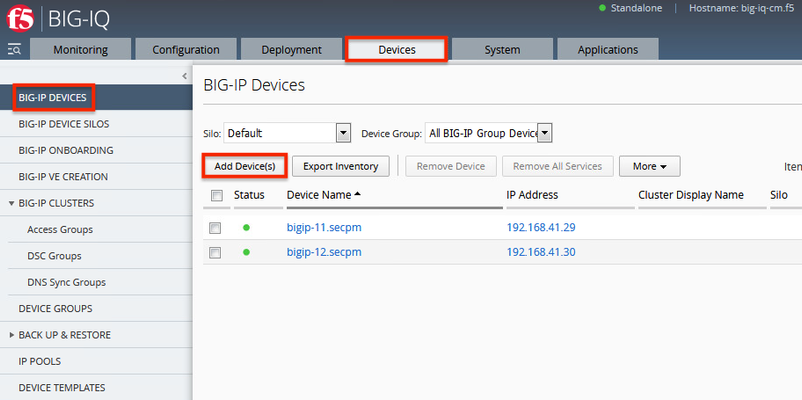
The F5 Beacon capabilities referenced in this article hosted on F5 Cloud Services are planning a migration to a new SaaS Platform - Check out the latest here. Introduction This article is part of a series on implementing Orchestrated Infrastructure Security. It includes High Availability, Central Management with BIG-IQ, Application Visibility with Beacon and the protection of critical assets using F5 Advanced WAF and Protocol Inspection (IPS) with AFM. It is also assumed that BIG-IQ is deployed, and basic network connectivity is working. If you need help setting up BIG-IQ for the first time, refer to the Dev/Central article series Implementing SSL Orchestrator here. That article covers SSL Orchestrator but the procedure to add Advanced WAF and AFM to BIG-IQ is the same. This article focuses on configuring BIG-IQ version 7.1.0 to manage F5 Advanced WAF, AFM and SSL Orchestrator. It covers management of BIG-IP running version 15.1.0.4 and SSL Orchestrator version 7.4.9, and version 16.0.0 with AFM and Advanced WAF. Please forgive me for using SSL and TLS interchangeably in this article. This article is divided into the following high level sections: Import BIG-IP Devices into BIG-IQ Service Import Error Resolution Schedule regular backups of BIG-IP devices Push backups to BIG-IP device Import BIG-IP Devices into BIG-IQ From the BIG-IQ GUI go to Devices > BIG-IP Devices. This is where you add new devices to be managed by BIG-IQ. You should add the two SSL Orchestrator’s using the Dev/Central article above. Click Add Device(s) to add Advanced WAF and AFM devices. Select the option to Add BIG-IP device(s) and automatically discover and import services. Then click Add Devices. Enter the IP Addresses of the Devices you want to add, 192.168.41.3 and 192.168.41.4 in this example (use the Plus sign to add another IP address field). These are the two AFM devices. Enter the username and password to access these devices. Under Services check the box for Network Security (AFM) then scroll down. Check the box to enable Statistics Collection. You can configure a Zone and/or Cluster Display Name if desired. Click Save and Close. Your screen should look like the following. Click Add Devices so we can add the two Advanced WAFs. Enter the IP Addresses of the Devices you want to add, 192.168.41.21 and 192.168.41.22 in this example (use the Plus sign to add another IP address field). These are the two Advanced WAF devices. Enter the username and password to access these devices. Under Services check the box for Web Application Security (ASM) then scroll down. Check the box to enable Statistics Collection. You can configure a Zone and/or Cluster Display Name if desired. Click Save and Close. Click Discover and Import. You should see a Progress screen. Click Close. When complete, your screen should look similar to the following.= Service Import Error Resolution Some devices had errors during Import. Click the first one to resolve it. There was a conflict importing SSM. Check the box to create a snapshot of the configuration then click Import. The following items were changed on the BIG-IP. You can choose to import these into the BIG-IQ by selecting Set all BIG-IP. Click Continue. A dialog screen will present you with more information about what you’re doing. Click Resolve. Click Import to complete the import process. You may want to create a Snapshot of the configuration by checking the box. The BIG-IP Devices screen should look like this. The Advanced WAF device has been successfully imported. Repeat this process for any devices with an import error. When all Devices are successfully imported the screen should look like this. Schedule regular backups of BIG-IP Devices Now is a good time to schedule regular Backups. Check the box next to Status to select all the BIG-IPs. Click the down Arrow next to More and select Schedule Backup. Give the Backup a name, Backup_all in this example. There are several options here that you may wish to enable. For Local Retention Policy, it’s not a bad idea to keep multiple backups, 3 in this example. The Start Date and time can be adjusted to suit your needs. The Devices should automatically be selected. You can optionally enable the Archiving of Backups to an external SCP or SFTP server. Click Save & Close. Push backups to BIG-IP Device At some point you may need to restore one of your BIG-IP devices from a backup. To do this select the Devices tab > Back Up & Restore > Backup Files. From here you can view the different backup files. You can also Compare, Download, Restore or Delete backup files. Select the backup you would like to restore then click Restore. You will be presented with a confirmation message warning you that the configuration of the device is about to be overwritten from the backup. Click Restore to proceed. While the device is being restored you will see the following. Select BIG-IP Devices to check the status of the device when the restore is complete. Summary In this article you learned how to import BIG-IP devices into BIG-IQ, import the BIG-IP Services and schedule regular backups of the BIG-IP devices. Next Steps Click Next to proceed to the next article in the series.651Views1like0CommentsThe Full-Proxy Data Center Architecture
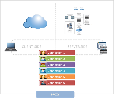
Why a full-proxy architecture is important to both infrastructure and data centers. In the early days of load balancing and application delivery there was a lot of confusion about proxy-based architectures and in particular the definition of a full-proxy architecture. Understanding what a full-proxy is will be increasingly important as we continue to re-architect the data center to support a more mobile, virtualized infrastructure in the quest to realize IT as a Service. THE FULL-PROXY PLATFORM The reason there is a distinction made between “proxy” and “full-proxy” stems from the handling of connections as they flow through the device. All proxies sit between two entities – in the Internet age almost always “client” and “server” – and mediate connections. While all full-proxies are proxies, the converse is not true. Not all proxies are full-proxies and it is this distinction that needs to be made when making decisions that will impact the data center architecture. A full-proxy maintains two separate session tables – one on the client-side, one on the server-side. There is effectively an “air gap” isolation layer between the two internal to the proxy, one that enables focused profiles to be applied specifically to address issues peculiar to each “side” of the proxy. Clients often experience higher latency because of lower bandwidth connections while the servers are generally low latency because they’re connected via a high-speed LAN. The optimizations and acceleration techniques used on the client side are far different than those on the LAN side because the issues that give rise to performance and availability challenges are vastly different. A full-proxy, with separate connection handling on either side of the “air gap”, can address these challenges. A proxy, which may be a full-proxy but more often than not simply uses a buffer-and-stitch methodology to perform connection management, cannot optimally do so. A typical proxy buffers a connection, often through the TCP handshake process and potentially into the first few packets of application data, but then “stitches” a connection to a given server on the back-end using either layer 4 or layer 7 data, perhaps both. The connection is a single flow from end-to-end and must choose which characteristics of the connection to focus on – client or server – because it cannot simultaneously optimize for both. The second advantage of a full-proxy is its ability to perform more tasks on the data being exchanged over the connection as it is flowing through the component. Because specific action must be taken to “match up” the connection as its flowing through the full-proxy, the component can inspect, manipulate, and otherwise modify the data before sending it on its way on the server-side. This is what enables termination of SSL, enforcement of security policies, and performance-related services to be applied on a per-client, per-application basis. This capability translates to broader usage in data center architecture by enabling the implementation of an application delivery tier in which operational risk can be addressed through the enforcement of various policies. In effect, we’re created a full-proxy data center architecture in which the application delivery tier as a whole serves as the “full proxy” that mediates between the clients and the applications. THE FULL-PROXY DATA CENTER ARCHITECTURE A full-proxy data center architecture installs a digital "air gap” between the client and applications by serving as the aggregation (and conversely disaggregation) point for services. Because all communication is funneled through virtualized applications and services at the application delivery tier, it serves as a strategic point of control at which delivery policies addressing operational risk (performance, availability, security) can be enforced. A full-proxy data center architecture further has the advantage of isolating end-users from the volatility inherent in highly virtualized and dynamic environments such as cloud computing . It enables solutions such as those used to overcome limitations with virtualization technology, such as those encountered with pod-architectural constraints in VMware View deployments. Traditional access management technologies, for example, are tightly coupled to host names and IP addresses. In a highly virtualized or cloud computing environment, this constraint may spell disaster for either performance or ability to function, or both. By implementing access management in the application delivery tier – on a full-proxy device – volatility is managed through virtualization of the resources, allowing the application delivery controller to worry about details such as IP address and VLAN segments, freeing the access management solution to concern itself with determining whether this user on this device from that location is allowed to access a given resource. Basically, we’re taking the concept of a full-proxy and expanded it outward to the architecture. Inserting an “application delivery tier” allows for an agile, flexible architecture more supportive of the rapid changes today’s IT organizations must deal with. Such a tier also provides an effective means to combat modern attacks. Because of its ability to isolate applications, services, and even infrastructure resources, an application delivery tier improves an organizations’ capability to withstand the onslaught of a concerted DDoS attack. The magnitude of difference between the connection capacity of an application delivery controller and most infrastructure (and all servers) gives the entire architecture a higher resiliency in the face of overwhelming connections. This ensures better availability and, when coupled with virtual infrastructure that can scale on-demand when necessary, can also maintain performance levels required by business concerns. A full-proxy data center architecture is an invaluable asset to IT organizations in meeting the challenges of volatility both inside and outside the data center. Related blogs & articles: The Concise Guide to Proxies At the Intersection of Cloud and Control… Cloud Computing and the Truth About SLAs IT Services: Creating Commodities out of Complexity What is a Strategic Point of Control Anyway? The Battle of Economy of Scale versus Control and Flexibility F5 Friday: When Firewalls Fail… F5 Friday: Platform versus Product5KViews1like1Comment
Two-Factor Authentication With Google Authenticator And LDAP
Introduction Earlier this year Google released their time-based one-time password (TOTP) solution named Google Authenticator. A TOTP is a single-use code with a finite lifetime that can be calculated by two parties (client and server) using a shared secret and a synchronized clock (see RFC 4226 for additional information). In the case of Google Authenticator, the TOTP are generated using a software (soft) token on a mobile device. Google currently offers applications for the Apple iPhone, Android-based devices, and Blackberry handsets. A user authenticating with a Google Authenticator-enabled service will require the possession of this software token. In order for the token to be effective, it must not be able to be duplicated and the shared secret should be closely guarded. Google Authenticator’s soft token solution offer a number of advantages over other commercially available solutions. It is free to use (all applications are free to download), the TOTP algorithm is open source, well-known, and well-tested, and finally it does not require a dedicated server for processing tokens. While certain potential weakness in SHA-1 have been identified, none of them can be exploited within the 30-second timeframe of the TOTP’s usability. For all intents and purposes, SHA-1 is reasonably secure, well-tested, and purpose-appropriate for this application. The algorithm however is only as secure as the users and administrators are at protecting the shared secret used in token processing. Calculating The Google Authenticator TOTP The Google Authenticator TOTP is calculated by generating an HMAC-SHA1 token, which uses a 10-byte base32-encoded shared secret as a key and Unix time (epoch) divided into a 30 second interval as inputs. The resulting 80-byte token is converted to a 40-character hexadecimal string, the least significant (last) hex digit is then used to calculate a 0-15 offset. The offset is then used to read the next 8 hex digits from the offset. The resulting 8 hex digits are then AND’d with 0x7FFFFFFF (2,147,483,647), then the modulo of the resultant integer and 1,000,000 is calculated, which produces the correct code for that 30 seconds period. Base32 encoding and decoding were covered in my previous Tech Tip titled Base32 Encoding And Decoding With iRules . The Tech Tip details the process for decoding a user’s base32-encoded key to binary as well as converting a binary key to base32. The HMAC-SHA256 token calculation iRule was originally submitted by Nat to the Codeshare on DevCentral. The iRule was slightly modified to support the SHA-1 algorithm, but is otherwise taken directly from the pseudocode outlined in RFC 2104. These two pieces of code contribute the bulk of the processing of the Google Authenticator code. The rest is done with simple bitwise and arithmetic functions. Google Authenticator Two-Factor Authentication Process Installing Google Authenticator Two-Factor Authentication The installation of Google Authenticator two-factor authentication on your BIG-IP is divided into six sections: creating an LDAP authentication configuration, configuring an LDAP (Active Directory) authentication profile, testing your authentication profile, adding the Google Authenticator iRule and “user_to_google_auth” mapping data group, attaching iRule to the authentication profile, and finally generating soft tokens for your users. The process is broken out into steps as trying to complete all the sections in tandem can be difficult to troubleshoot. Creating An LDAP (Active Directory) Authentication Configuration The LDAP profile we will configure will be extremely basic: no SSL, no Active Directory, etc. A detailed walkthrough for more advanced deployments can be found in our best practices guide: Configuring LDAP remote authentication for Active Directory . 1. Login to your BIG-IP using administrator credentials 2. Navigate to Local Traffic > Profiles > Authentication > Configurations 3. Click “Create” in the upper right-hand corner 4. Select “LDAP” from the “Type” drop-down menu 5. Now fill in the fields with your environment-specific values: Name: ldap.f5test.local Type: LDAP Remote LDAP Tree: dc=f5test, dc=local Host(s): <IP address(es) of LDAP server(s)> Service Port: 389 (default) LDAP Version: 3 (default) Bind DN: cn=ldap_bind_acct, dc=f5test, dc=local (if your LDAP server allows anonymous binds you may not need this option) Bind Password: <admin password> Confirm Bind Password: <admin password> 6. Click “Finished” to save the configuration Configuring An LDAP (Active Directory) Authentication Profile 1. Navigate to Local Traffic > Profiles > Authentication > Profiles 2. Click “Create” in the upper right-hand corner 3. Select “LDAP” from the “Type” drop-down menu 4. Fill in fields with appropriate values: Name: ldap.f5test.local Type: LDAP Configuation: ldap.f5test.local (select previously named configuration from drop-down) Rule: (leave this unchecked and not enabled for now, but this is where we will enable the Google Authenticator iRule shortly) 5. Click “Finished” Test Your Authentication Profile 1. Create a basic HTTP virtual server with your LDAP authentication profile enabled on the virtual 2. Access your virtual from a web browser and you should be prompted with an HTTP Basic Authentication credential form 3. Test with known-working credentials, if everything works you’re good to go, if not you’ll need to troubleshoot the authentication issue Adding the Google Authenticator iRule 1. Go to the DevCentral Codeshare and download the Google Authenticator iRule 2. Navigate to Local Traffic > iRules > iRule List 3. Click “Create” in the upper right-hand corner 4. Name your iRule “google_authenticator_plus_ldap_two_factor” and paste the iRule into “Definition” section 5. Click “Finished” when you’re done Attaching The Google Authenticator iRule To Your Authentication Profile 1. Go back to the “Authentication Profile” section by browsing to Local Traffic > Profiles > Authentication > Profiles 2. Select your LDAP profile from the list 3. Now attach select the “google_authenticator_plus_ldap_two_factor” iRule from the “Rule” drop-down 4. Click “Finished” Generating Software Tokens For Users In addition to the Google Authenticator iRule we also wrote a Google Authenticator Soft Token Generator iRule that will generate soft tokens for your users. The iRule can be added directly to an HTTP virtual server without a a pool and accessed directly to create tokens. There are a few available fields in the generator: account, pre-defined secret, and a QR code option. The “account” field defines how to label the soft token within the user’s mobile device and can be useful if the user has multiple soft token on the same device (I have 3 and need to label them to keep them straight). A 10-byte string can be used as a pre-defined secret for conversion to a base32-encoded key. We will advise you against using a pre-defined key because a key known to the user is something they know (as opposed to something they have) and could be potentially regenerate out-of-band thereby nullifying the benefits of two-factor authentication. Lastly, there is an option to generate a QR code by sending an HTTPS request to Google and returning the QR code as an image. While this is convenient, this could be seen as insecure since it may wind up in Google’s logs somewhere. You’ll have to decide if that is a risk you’re willing to take for the convenience it provides. Once the token has been generated, it will need to be added to a data group on the BIG-IP: 1. Navigate to Local Traffic > iRules > Data Group Lists 2. Select “Create” from the upper right-hand corner if the data group does not yet exist. If it exists, just select it from the list. 3. Name the data group “user_to_google_auth” (data group name can be changed in the RULE_INIT section of the Google Authenticator iRule) 4. The type of data group will be “string” 5. Type the “username” into the “string” field and paste the “Google Authenticator key” into the “value” field 6. Click “Add” and you the username/key pair should appear in the list as such: user := ONSWG4TFOQYTEMZU 7. Click “Finished” when all your username/key pairs have been added. Your user can scan the QR code or type it into their device manually. After they scan the QR code, the account name should appear along with the TOTP for the account. The image below is how the soft token appears in the Google Authenticator iPhone application: Once again, do not let the user leave with a copy of the plain text key. Knowing their key value will negate the value of having the token in the first place. Once the key has been added to the BIG-IP, the user’s device, and they’ve tested their access, destroy any reference to the key outside the BIG-IPs data group.If you’re worried about having the keys in plain text on the BIG-IP, they can be encrypted with AES or stored off-box in LDAP and only queried via secure connection. This is beyond the scope of this article, but doable with iRules. Testing and Troubleshooting There are a lot of moving pieces in this iRule so troubleshooting can be a bit daunting at first glance, but because all of the pieces can be separated into their constituents the problem is usually identified quickly. There are five pieces that make up this solution: the LDAP service, the BIG-IP LDAP profile, the Google Authenticator iRule, the “user_to_google_auth” mapping data group, and finally the soft token. Try to separate them from each other to expedite the troubleshooting process. Here are a few helpful hints in troubleshooting potential issues: 1. Are all the clocks synchronized? The BIG-IP and LDAP server can be tested from the command line by running ‘ntpdate –q pool.ntp.org’. If the clocks are more than a few milliseconds off, they’ll need to be adjusted. An NTP server should be configured for all devices. Likewise the user’s mobile device must be configured to use network time or else the calculated value will always be wrong. Remember that timezones do not matter when using Unix time. 2. Is basic LDAP working without the iRule attached? Before ever touching any of the Google Authenticator related iRules, data groups, devices, etc. your LDAP configuration should be in working order. If you’re having problems finding the issue, enable “debug logging” at the bottom of the LDAP authentication configuration page on your BIG-IP and tail the logs on your LDAP server. Revisit the best practices guide if you are still unsure about any configuration options. 3. Turn on (or increase) logging for Google Authenticator iRule. In the RULE_INIT section of the Google Authenticator iRule, there is a debug logging option. Set it to ‘2’ and all actions from the iRule will be logged to /var/log/ltm. If you see one particular area that is consistently hanging, investigate it further. Conclusion With every passing day system security becomes a greater concern. Today’s attacks are far more sophisticated and costly than those of days past. With all the stories of stolen laptops and other devices in the field, it is a little easier to sleep as a systems administrator knowing that a tech-aware thief has one more hurdle to surpass in an effort to compromise your infrastructure. The implementation costs of deploying two-factor authentication with Google Authenticator in an existing F5 infrastructure are very low assuming your employees have company-issued mobile devices. The cost can be deduced to the man hours required to install this iRule and generate tokens for your users. The cost is almost certainly less than that of a single incident of a compromise account. Until next time, batten down the hatches and get that two-factor project underway that’s been on the backburner for two years. Code and References Google Authenticator iRule – Documentation and code for the iRule used in this Tech Tip Google Authenticator Soft Token Generator iRule – iRule for generating soft tokens for users RFC 4226 - HOTP: An HMAC-Based One-Time Password Algorithm RFC 2104 - HMAC: Keyed-Hashing for Message Authentication RFC 4648 - The Base16, Base32, and Base64 Data Encodings SOL11072 - Configuring LDAP remote authentication for Active Directory7.7KViews1like12Comments
F5 in AWS Part 4 - Orchestrating BIG-IP Application Services with Open-Source tools
Updated for Current Versions and Documentation Part 1 : AWS Networking Basics Part 2: Running BIG-IP in an EC2 Virtual Private Cloud Part 3: Advanced Topologies and More on Highly-Available Services Part 4: Orchestrating BIG-IP Application Services with Open-Source Tools Part 5: Cloud-init, Single-NIC, and Auto Scale Out of BIG-IP in v12 The following post references code hosted at F5's Github repository f5networks/aws-deployments. This code provides a demonstration of using open-source tools to configure and orchestrate BIG-IP. Full documentation for F5 BIG-IP cloud work can be found at Cloud Docs: F5 Public Cloud Integrations. So far we have talked above AWS networking basics, how to run BIG-IP in a VPC, and highly-available deployment footprints. In this post, we’ll move on to my favorite topic, orchestration. By this point, you probably have several VMs running in AWS. You’ve lost track of which configuration is setup on which VM, and you have found yourself slowly going mad as you toggle between the AWS web portal and several SSH windows. I call this ‘point-and-click’ purgatory. Let's be blunt, why would you move to cloud without realizing the benefits of automation, of which cloud is a large enabler. If you remember our second article, we mentioned CloudFormation templates as a great way to deploy a standardized set of resources (perhaps BIG-IP + the additional virtualized network resources) in EC2. This is a great start, but we need to configure these resources once they have started, and we need a way to define and execute workflows which will run across a set of hosts, perhaps even hosts which are external to the AWS environment. Enter the use of open-source configuration management and workflow tools that have been popularized by the software development community. Open-source configuration management and AWS APIs Lately, I have been playing with Ansible, which is a python-based, agentless workflow engine for IT automation. By agentless, I mean that you don’t need to install an agent on hosts under management. Ansible, like the other tools, provides a number of libraries (or “modules”) which provide the ability to manage a diverse collection of remote systems. These modules are typically implemented through the use of API calls, often over HTTP. Out of the box, Ansible comes with several modules for managing resources in AWS. While the EC2 libraries provided are useful for basic orchestration use cases, we decided it would be easier to atomically manage sets of resources using the CloudFormation module. In doing so, we were able to deploy entire CloudFormation stacks which would include items like VPCs, networking elements, BIG-IP, app servers, etc. Underneath the covers, the CloudFormation: Ansible module and our own project use the python module to interact with AWS service endpoints. Ansible provides some basic modules for managing BIG-IP configuration resources. These along with libraries for similar tools can be found here: Ansible Puppet SaltStack In the rest of this post, I’ll discuss some work colleagues and I have done to automate BIG-IP deployments in AWS using Ansible. While we chose to use Ansible, we readily admit that Puppet, Chef, Salt and whatever else you use are all appropriate choices for implementing deployment and configuration management workflows for your network. Each have their upsides and downsides, and different tools may lend themselves to different use cases for your infrastructure. Browse the web to figure out which tool is right for you. Using Standardized BIG-IP Interfaces Speaking of APIs, for years F5 has provided the ability to programmatically configure BIG-IP using iControlSOAP. As the audiences performing automation work have matured, so have the weapons of choice. The new hot ticket is REST (Representational State Transfer), and guess what, BIG-IP has a REST interface (you can probably figure out what it is called). Together, iControlSOAP and iControlREST give you the power to manage nearly every configuration element and feature of BIG-IP. These interfaces become extremely powerful when you combine them with your favorite open-source configuration management tool and a cloud that allows you to spin up and down compute and networking resources. In the project described below, we have also made use of iApps using iControlRest as a way to create a standard virtual server configuration with the correct policies and profiles. The documentation in Github describes this in detail, but our approach shows how iApps provide a strongly supported approach for managing network policy across engineering teams. For example, imagine that a team of software engineers has written a framework to deploy applications. You can package the network policy into iApps for various types of apps, and pass these to the teams writing the deployment framework. Implementing a Service Catalog To pull the above concepts together, a colleague and I put together the aws-deployments project. The goal was to build a simple service catalog which would enable a user to deploy a containerized application in EC2 with BIG-IP network services sitting in front. This is example code that is not supported by F5 support but is a proof of concept to show how you can fully automate production-like deployments in AWS. Some highlights of the project include: Use of iControlRest and iControlSoap within Ansible playbooks to setup advanced topologies of BIG-IP in AWS. Automated deployment of a basic ASM web application firewall policy to protect a vulnerable web app (Hackazon. Use of iApps to manage virtual server configurations, including the WAF policy mentioned above. Figure 1 - Generic Architecture for automating application deployments in public or private cloud In examination of the code, you will see that we provide the opportunity to provision all the development models outlined in our earlier post (a single standalone VE, standalones BIG-IP VEs striped availability zones, clusters within an availability zone, etc). We used Ansible and the interfaces on BIG-IP to orchestrate the workflows assoiated with these deployment models. To perform the clustering step, we have used the iControlSoap interface on BIG-IP. The final set of technology used is depicted in Figure 3. Figure 2 - Technologies used in the aws-deployments project on Github Read the Code and Test It Yourself All the code I have mentioned is available at f5networks/aws-deployments. We encourage you to download and run the code for yourself. Instructions for setting up a development environment which includes the necessary dependencies is easy. We have packaged all the dependencies for use with either Vagrant or Docker as development tools. The instructions for either of these approaches can be found in the README.md or in the /docs directory. The following video shows an end-to-end usage example. (Keep in mind that the code has been updated since this video was produced). At the end of the day, our goal for this work was to collect customer feedback. Please provide some by leaving a comment below, or by filing ‘pull requests’ or ‘issues’ in Github. In the next few weeks, we will be updating the project to include the Hackazon app mentioned above, show how to cluster BIG-IP across availability zones, and how to deploy an ASM profile with an iApp. Have fun!1.6KViews1like3Comments