deployment
290 TopicsHow to get a F5 BIG-IP VE Developer Lab License
(applies to BIG-IP TMOS Edition) To assist operational teams teams improve their development for the BIG-IP platform, F5 offers a low cost developer lab license. This license can be purchased from your authorized F5 vendor. If you do not have an F5 vendor, and you are in either Canada or the US you can purchase a lab license online: CDW BIG-IP Virtual Edition Lab License CDW Canada BIG-IP Virtual Edition Lab License Once completed, the order is sent to F5 for fulfillment and your license will be delivered shortly after via e-mail. F5 is investigating ways to improve this process. To download the BIG-IP Virtual Edition, log into my.f5.com (separate login from DevCentral), navigate down to the Downloads card under the Support Resources section of the page. Select BIG-IP from the product group family and then the current version of BIG-IP. You will be presented with a list of options, at the bottom, select the Virtual-Edition option that has the following descriptions: For VMware Fusion or Workstation or ESX/i: Image fileset for VMware ESX/i Server For Microsoft HyperV: Image fileset for Microsoft Hyper-V KVM RHEL/CentoOS: Image file set for KVM Red Hat Enterprise Linux/CentOS Note: There are also 1 Slot versions of the above images where a 2nd boot partition is not needed for in-place upgrades. These images include _1SLOT- to the image name instead of ALL. The below guides will help get you started with F5 BIG-IP Virtual Edition to develop for VMWare Fusion, AWS, Azure, VMware, or Microsoft Hyper-V. These guides follow standard practices for installing in production environments and performance recommendations change based on lower use/non-critical needs for development or lab environments. Similar to driving a tank, use your best judgement. Deploying F5 BIG-IP Virtual Edition on VMware Fusion Deploying F5 BIG-IP in Microsoft Azure for Developers Deploying F5 BIG-IP in AWS for Developers Deploying F5 BIG-IP in Windows Server Hyper-V for Developers Deploying F5 BIG-IP in VMware vCloud Director and ESX for Developers Note: F5 Support maintains authoritative Azure, AWS, Hyper-V, and ESX/vCloud installation documentation. VMware Fusion is not an official F5-supported hypervisor so DevCentral publishes the Fusion guide with the help of our Field Systems Engineering teams.100KViews14likes152CommentsImplementing SSL Orchestrator - High Level Considerations
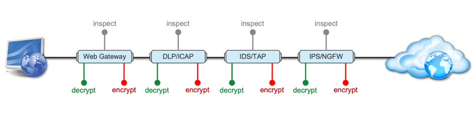
Introduction This article is the beginning of a multi-part series on implementing BIG-IP SSL Orchestrator. It includes high availability and central management with BIG-IQ. Implementing SSL/TLS Decryption is not a trivial task. There are many factors to keep in mind and account for, from the network topology and insertion point, to SSL/TLS keyrings, certificates, ciphersuites and on and on. This article focuses on pre-deployment tasks and preparations for SSL Orchestrator. This article is divided into the following high level sections: Solution Overview Customer Use Case Architecture & Network Topology Please forgive me for using SSL and TLS interchangeably in this article. Software versions used in this article: BIG-IP Version: 14.1.2 SSL Orchestrator Version: 5.5 BIG-IQ Version: 7.0.1 Solution Overview Data transiting between clients (PCs, tablets, phones etc.) and servers is predominantly encrypted with Secure Socket Layer (SSL) and its evolution Transport Layer Security (TLS)(ref. Google Transparency Report). Pervasive encryption means that threats are now predominantly hidden and invisible to security inspection unless traffic is decrypted. The decryption and encryption of data by different devices performing security functions potentially adds overhead and latency. The picture below shows a traditional chaining of security inspection devices such as a filtering web gateway, a data loss prevention (DLP) tool, and intrusion detection system (IDS) and next generation firewall (NGFW). Also, TLS/SSL operations are computationally intensive and stress the security devices’ resources. This leads to a sub-optimal usage of resource where compute time is used to encrypt/decrypt and not inspect. F5’s BIG-IP SSL Orchestrator offers a solution to optimize resource utilization, remove latency, and add resilience to the security inspection infrastructure. F5 SSL Orchestrator ensures encrypted traffic can be decrypted, inspected by security controls, then re-encrypted—delivering enhanced visibility to mitigate threats traversing the network. As a result, you can maximize your security services investment for malware, data loss prevention (DLP), ransomware, and next-generation firewalls (NGFW), thereby preventing inbound and outbound threats, including exploitation, callback, and data exfiltration. The SSL Orchestrator decrypts the traffic and forwards unencrypted traffic to the different security devices for inspection leveraging its optimized and hardware-accelerated SSL/TLS stack. As shown below the BIG-IP SSL Orchestrator classifies traffic and selectively decrypts traffic. It then forwards it to the appropriate security functions for inspection. Finally, once duly inspected the traffic is encrypted and sent on its way to the resource the client is accessing. Deploying F5 and inline security tools together has the following benefits: Traffic Distribution for load sharing Improve the scalability of inline security by distributing the traffic across multiple Security appliances, allowing them to share the load and inspect more traffic. Agile Deployment Add, remove, and/or upgrade Security appliances without disrupting network traffic; converting Security appliances from out-of-band monitoring to inline inspection on the fly without rewiring. Customer Use Case This document focuses on the implementation of BIG-IP SSL Orchestrator to process SSL/TLS encrypted traffic and forward it to a security inspection/enforcement devices. The decryption and forwarding behavior are determined by the security policy. This ensures that only targeted traffic is decrypted in compliance with corporate and regulator policy, data privacy requirements, and other relevant factors. The configuration supports encrypted traffic that originates from within the data center or the corporate network. It also supports traffic originating from clients outside of the security perimeter accessing resources inside the corporate network or demilitarized zone (DMZ) as depicted below. The decrypted traffic transits through different inspection devices for inbound and outbound traffic. As an example, inbound traffic is decrypted and processed by F5’s Advanced Web Application Firewall (F5 Advanced WAF) as shown below. * Can be encrypted or cleartext as needed As an example, outbound traffic is decrypted and sent to a next generation firewall (NGFW) for inspection as shown in the diagram below. The BIG-IP SSL Orchestrator solution offers 5 different configuration templates. The following topologies are discussed in Network Insertion Use Cases. L2 Outbound L2 Inbound L3 Outbound L3 Inbound L3 Explicit Proxy Existing Application In the use case described herein, the BIG-IP is inserted as layer 3 (L3) network device and is configured with an L3 Outbound Topology. Architecture & Network Topology The assumption is that, prior to the insertion of BIG-IP SSL Orchestrator into the network (in a brownfield environment), the network looks like the one depicted below. It is understood that actual networks will vary, that IP addressing, L2 and L3 connectivity will differ, however, this is deemed to be a representative setup. Note: All IP addressing in this document is provided as examples only. Private IP addressing (RFC 1918) is used as in most corporate environments. Note: the management network is not depicted in the picture above. Further discussion about management and visibility is the subject of Centralized Management below. The following is a description of the different reference points shown in the diagram above. a. This is the connection of the border routers that connect to the internet and other WAN and private links. Typically, private IP addressing space is used from the border routers to the firewalls. b. The border switching connects to the corporate/infrastructure firewall. Resilience is built into this switching layer by implementing 2 link aggregates (LAG or Port Channel ®). c. The “demilitarized zone”(DMZ) switches are connected to the firewall. The DMZ network hosts application that are accessible from untrusted networks such as the Internet. d. Application server connect into the DMZ switch fabric. e. Firewalls connect into the switch fabric. Typically core and distribution infrastructure switching will provide L2 and L3 switching to the enterprise (in some case there may be additional L3 routing for larger enterprises/entities that require dynamic routing and other advanced L3 services. f. The connection between the core and distribution layers are represented by a bus on the figure above because the actual connection schema is too intricate to picture. The writer has taken the liberty of drawing a simplified representation. Switches actually interconnect with a mixture of link aggregation and provide differentiated switching using virtualization (e.g. VLAN tagging, 802.1q), and possibly further frame/packet encapsulation (e.g. QinQ, VxLAN). g. The core and distribution switching are used to create 2 broadcast domains. One is the client network, and the other is the internal application network. h. The internal applications are connected to their own subnet. The BIG-IP SSL Orchestrator solution is implemented as depicted below. In the diagram above, new network connections are depicted in orange (vs. blue for existing connections). Similarly to the diagram showing the original network, the switching for the DMZ is depicted using a bus representation to keep the diagram simple. The following discusses the different reference points in the diagram above: a. The BIG-IP SSL Orchestrator is connected to the core switching infrastructure A new VLAN and network are created on the core switching infrastructure to connect to the firewalls (North) to the BIG-IP SSL Orchestrator devices. b. The client network (South) is connected to the BIG-IP via a second VLAN and network. c. The SSL Orchestrator devices are connected to a newly created inspection network. This network is kept separate from the rest of the infrastructure as client traffic transits through the inspection devices unencrypted. As an example, Web Application Firewalls (BIG-IP ASM) are used to filter inbound traffic. d. The LAN configuration for the connection to the BIG-IP ASM is as depicted below. e. The NGFW is connected to the INSPECTION switching network in such a manner that traffic traverses it when the BIG-IP SSL Orchestrator is configured to push traffic for inspection. Summary This article should be a good starting point for planning your initial SSL Orchestrator deployment. We covered the solution overview and use cases. The network topology and architecture was explained with the help of diagrams. Next Steps Click Next to proceed to the next article in the series5KViews7likes4CommentsExtend visibility - BIG-IP joins forces with CrowdStrike
Introduction The traditional focus in cybersecurity has prioritized endpoints like laptops and mobiles with EDR, as they are key entry points for intrusions. Modern threats target the full network infrastructure, like routers, ADCs, firewalls, servers, VMs, and cloud instances, as interconnected endpoints. All network software is a potential target in today’s sprawling attack surface. Summarizing some of those blind points below, Servers, including hardware, VMs, and cloud instances: Often under-monitored, rapid spin-up creates ephemeral risks for exfiltration and lateral movement. Network appliances: Enable traffic redirection, data sniffing, or backdoors, if compromised. Application delivery components: Vulnerable to session hijacking, code injection, or DDoS, due to high-traffic processing. Falcon sensor integration In this section, we go through download and installation steps, and observe how the solution works with detecting/blocking malicious packages. For more information, follow our KB articles, https://my.f5.com/manage/s/article/K000157015 Related content K000157015: Getting Started with Falcon sensor for BIG-IP K000156881: Install Falcon sensor for BIG-IP on the BIG-IP system K000157014: F5 Support for Falcon for BIG-IP https://www.f5.com/partners/technology-alliances/crowdstrike 262Views4likes0Comments
Quick Deployment: Deploy F5 CIS/F5 IngressLink in a Kubernetes cluster on AWS
Summary This article describes how to deploy F5 Container Ingress Services (CIS) and F5 IngressLink with NGINX Ingress Controller on AWS cloud quickly and predictably. All you need to begin with are your AWS credentials. (15-35 mins). Problem Statement Deploying F5 IngressLink is quick and simple. However, to do so, you must first deploy the following resources: AWS resources such as VPC, subnets, security groups and more. A Kubernetes cluster on AWS A BIG-IP Instance F5 Container Ingress Services, CIS NGINX Ingress Controller Application pods Many times, we want to spin up a Kubernetes cluster with the resources listed above for a quick demo, educational purposes, experimental testing or to simply run a command to view its output. However, the creation and deletion processes are both however error prone and time consuming. In addition, we don't want the overhead and cost of maintaining the cluster and keeping the instances/virtual machines running. And we'd like to tear down the deployment as soon as we're done. Solution We need to automate and integrate predictably the creation steps described in F5 Clouddocs: To deploy BIG-IP CIS and F5 IngressLink. NGINX documentation: To deploy NGINX Ingress Controller. Refer to my GitHub repository to perform this using either: Disclaimer: The deployment in the GitHub repository is for demo or experimental purposes and not meant for production use or supported by F5 Support. For example, the Kubernetes nodes are configured to have public elastic IP addresses for easy access for troubleshooting. kops: kops takes about 6-8 mins to deploy a Kubernetes cluster on AWS. You can complete the BIG-IP CIS/Ingress Link deployment in about 15 mins. OR eksctl: eksctl takes about 25-28mins to deploy an EKS cluster on AWS. You can complete the BIG-IP CIS/Ingress Link deployment in about 35mins. If you don't need the Kubernetes resources eksctl creates, such as an EKS cluster managed by Amazon's EKS control plane and at least two subnets in different availability zones for resilience and so on, kops is a faster option. For any bugs, please raise an issue on GitHub.1.8KViews4likes2CommentsModernizing F5 BIG-IP Synchronized HA Pairs with Ansible Validated Content
I wanted to provide an update to a previous article I released a few months ago where we developed Ansible Automation Platform code to help with migrating Standalone Legacy platforms (non-iSeries, iSeries and Viprion Instances) to our Modern Architectures (rSeries and Velos) using F5OS Tenant instances. I am happy to announce that the code for Synchronized HA pairs has been completed, and we have uploaded it to Ansible Automation Hub as Validated Content. What is Ansible Automation Hub Validated Content? Ansible validated content collections contain pre-built YAML content (such as playbooks or roles) to address the most common automation use cases. You can use Ansible validated content out-of-the-box or as a learning opportunity to develop your skills. It's a trusted starting point to bootstrap your automation: use it, customize it, and learn from it. Due to the focus on customization and the intent for this content to be modified, it is not subject to the same support requirements as our certified collections. To this end, any issues with this content should be filed directly at the source repository for that collection. Why Synchronized HA Pairs? This is a very common use case for a lot of our customers who want resiliency and redundancy, especially for their applications and services. The biggest issue with migrating an HA Pair is that because of the way they are set up, things like Management IP Addresses and Master Keys are essential to the transition process. Even mismatched versions during upgrades cannot synchronize during the process of upgrading to major/minor releases. What does the updated Validated Code do? Standalone Migrations – Where you can change the Management IP, due to the nature of being a standalone device, an outage will occur during the transition period. o There are 2 options for Playbooks Single Playbook for the full migration 2 Parts where Part 1 – Does backups and does a big start stop of the unit Part 2 – Migrates the standalone device HA Pairs – Combined – This code is designed for a customer who just needs to transition both HA Units but isn’t concerned about an outage window. It will migrate both units at the same time to F5OS Tenants. The Playbooks for this Code are broken apart in specific areas Part 1 – Backup the Information Part 2 – Ensure Both Units are offline and Migrate both units at the same time. HA Pairs – Sequential – This code is designed for customers who need to migrate one unit at a time and maintain availability of their applications. It will migrate the Standby Unit first as part of the code When ready to transition the active unit, it will place it in Standby and make the Transitioned Standby unit the Active Node transferring services to it Then the previously Active Unit (now standby) will be migrated There are playbooks to the Code to break apart specific areas of the transition Part 1 – Backup the Information Part 2 – Ensure the Standby Devices are offline (via Management IP) and Migrate the Standby Unit Part 3 – Transition the Standby to become the Active Unit and Begin Transitioning the New Standby Unit (Previously Active Unit) similarly to Part 2 This code has been tested and validated against many different platforms, and there are plans to continue testing for other use cases. The Transition can be Like-for-Like versioning (i.e. 16.1.x to 16.1.x) within the same family tree or can be an upgrade at the same time (i.e. 15.1.10 à 17.5.1.3 or even 21.0.0) These are Ansible Playbooks with supporting roles tailored for Red Hat Ansible Automation Platform. It’s built to perform a lift-and-shift migration of a F5 BIG-IP configuration from one device to another—with optional OS upgrades included. What is the future of the code? I plan on adding some Validation code to separate roles/playbooks so customers could have points of references for testing, i.e. (ping tests and pool tests) before and after the transition, QKView Backups, and other information provided on the state of the unit prior to transition to ensure when migrated it can be validated that everything is the way it was. Notes about the Code The code is not designed to handle Non-VLANed infrastructure (F5OS is designed to be multi-tenant and setup with VLANs to deal with Multi-Tenancy) If your BIG-IPs use Untagged networks, they will need to be migrated to VLANed prior to using this code. Has not been validated/tested with FIPS-based environments Has not been validated/tested F5 DNS environments – Coming Soon HA Pairs must retain the Management IP address from source to destination; the code will ensure that the source device is powered off prior to transitioning it. Cool Additions Override variables are allowed as extra_vars to create flexibility in your deployment override_cpu - This allows you to set the CPUs of the Tenant OS. If the memory override isn’t set, it will be set to the same formula that the F5OS Gui would calculate. DEFAULT is set to 4 CPU override_disk_size - This allows you to set the Disk Space of the Tenant OS. DEFAULT is set to 120GB override_memory - This allows you to set the Memory of the Tenant OS. Be warned if over-provisioned, the Tenant may not start. DEFAULT is calculated by the CPU counts formula used in the GUI. tenant_nodes - This allows you to set the slot for the Tenant OS if there are multiple slots associated with your F5OS Partition. DEFAULT is an array object and it is set to [1] cryptos - This allows you to set the Crypto on the Tenant OS to either enabled or disabled. DEFAULT is set to enabled Variables for deployments – the code is designed to utilize specific hostnames and group names to execute the code. These variables allow connectivity to BIGIP and F5OS Tenants. When creating these hosts, you will need to provide When creating hosts in AAP, you will need to provide the following information ansible_host: - This is the IP Address of the device of the host ansible_user: - This is the username to login to the device ansible_password: - this is the password to login to the device; if using a credential in AAP, you would associate that variables information here as a reference. i.e. Standalone deployments host_vars f5_destination_partition – This is the F5OS Partition information f5_destination_tenant – This is the F5OS Tenant information f5_source – This is the source device HA Pair Deployments group_vars ha_pair_destination_chassis – contains a group of 2 hosts for the destination tenants to be deployed to (can be 2 hosts with the same information or different) ha_pair_source – contains a group of 2 hosts for the source BIG-IP Devices in a synchronized HA Pair. ha_pair_source_dynamic - this group is created automatically throughout the code to program the new Tenant OSes after deployment (DOES NOT NEED TO BE CREATED) Demos/Information We have uploaded a new demo video below, you’ll see an migration of a synchronized HA Pair of BIG-IPs running as Viprion Tenants on F5 B2250 Blades running 15.1.10 transitioning to a pair of rSeries R5800s Tenant OSs running 17.5.1.x — demonstrating a smooth modernization process. Watch the synchronized HA migration Demo Video If you want to check out the information and demo video on the Standalone migrations, check out my other article at – Modernizing F5 Platforms with Ansible | DevCentral You can access the validated content via Ansible Automation Hub (Need Red Hat Account with AAP) https://console.redhat.com/ansible/automation-hub/repo/validated/f5networks/f5_platform_modernization/ Or you can access the direct code from our GitHub Repository https://github.com/f5devcentral/f5-bd-ansible-platform-modernization This project is built for the community/partners/system integrators — so as I always say, feel free to take it, fork it, and expand it. Let’s make F5 platform modernization as seamless and automated as possible!64Views3likes0CommentsUsing n8n To Orchestrate Multiple Agents
I’ve been heads-down building a series of AI step-by-step labs, and this one might be my favorite so far: a practical, cost-savvy “mixture of experts” architectural pattern you can run with n8n and self-hosted models on Ollama. The idea is simple. Not every prompt needs a heavyweight reasoning model. In fact, most don’t. So we put a small, fast model in front to classify the user’s request—coding, reasoning, or something else—and then hand that prompt to the right expert. That way, you keep your spend and latency down, and only bring out the big guns when you really need them. Architecture at a glance: Two hosts: one for your models (Ollama) and one for your n8n app. Keeping these separate helps n8n stay snappy while the model server does the heavy lifting. Docker everywhere, with persistent volumes for both Ollama and n8n so nothing gets lost across restarts. Optional but recommended: NVIDIA GPU on the model host, configured with the NVIDIA Container Toolkit to get the most out of inference. On the model server, we spin up Ollama and pull a small set of targeted models: deepseek-r1:1.5b for the classifier and general chit-chat deepseek-r1:7b for the reasoning agent (this is your “brains-on” model) codellama:latest for coding tasks (Python, JSON, Node.js, iRules, etc.) llama3.2:3b as an alternative generalist On the app server, we run n8n. Inside n8n, the flow starts with the “On Chat Message” trigger. I like to immediately send a test prompt so there’s data available in the node inspector as I build. It makes mapping inputs easier and speeds up debugging. Next up is the Text Classifier node. The trick here is a tight system, prompt and clear categories: Categories: Reasoning and Coding Options: When no clear match → Send to an “Other” branch Optional: You can allow multiple matches if you want the same prompt to hit more than one expert. I’ve tried both approaches. For certain, ambiguous asks, allowing multiple can yield surprisingly strong results. I attach deepseek-r1:1.5b to the classifier. It’s inexpensive and fast, which is exactly what you want for routing. In the System Prompt Template, I tell it: If a prompt explicitly asks for coding help, classify it as Coding If it explicitly asks for reasoning help, classify it as Reasoning Otherwise, pass the original chat input to a Generalist From there, each classifier output connects to its own AI Agent node: Reasoning Agent → deepseek-r1:7b Coding Agent → codellama:latest Generalist Agent (the “Other” branch) → deepseek-r1:1.5b or llama3.2:3b I enable “Retry on Fail” on the classifier and each agent. In my environment (cloud and long-lived connections), a few retries smooth out transient hiccups. It’s not a silver bullet, but it prevents a lot of unnecessary red Xs while you’re iterating. Does this actually save money? If you’re paying per token on hosted models, absolutely. You’re deferring the expensive reasoning calls until a small model decides they’re justified. Even self-hosted, you’ll feel the difference in throughput and latency. CodeLlama crushes most code-related queries without dragging a reasoning model into it. And for general questions—“How do I make this sandwich?”—A small generalist is plenty. A few practical notes from the build: Good inputs help. If you know you’re asking for code, say so. Your classifier and downstream agent will have an easier time. Tuning beats guessing. Spend time on the classifier’s system prompt. Small changes go a long way. Non-determinism is real. You’ll see variance run-to-run. Between retries, better prompts, and a firm “When no clear match” path, you can keep that variance sane. Bigger models, better answers. If you have the budget or hardware, plugging in something like Claude, GPT, or a higher-parameter DeepSeek will lift quality. The routing pattern stays the same. Where to take it next: Wire this to Slack so an engineering channel can drop prompts and get routed answers in place. Add more “experts” (e.g., a data-analysis agent or an internal knowledge agent) and expand your classifier categories. Log token counts/latency per branch so you can actually measure savings and adjust thresholds/models over time. This is a lab, not a production, but the pattern is production-worthy with the right guardrails. Start small, measure, tune, and only scale up the heavy models where you’re seeing real business value. Let me know what you build—especially if you try multi-class routing and send prompts to more than one expert. Some of the combined answers I’ve seen are pretty great. Here's the lab in our git, if you'd like to try it out for yourself. If video is more your thing, try this: Thanks for building along, and I’ll see you in the next lab. 179Views3likes0Comments
File Uploads and ASM
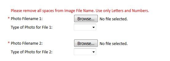
File Uploads through a WAF Let’s say we have a web application with a form field that permits the upload of arbitrary files. It would appear to the user similar to the below: Aside from photos, the application may permit users to upload Word documents, Excel spreadsheets, PDF’s, and so forth. This can cause many false positives when the web application is protected by ASM, because the uploaded files may: Contain attack signatures. Image files may be parsed as ASCII, and suspicious-looking strings detected; Word or Excel documents may contain XSS tags or SQL injection strings. After all, Mr. ‘Select’ – ‘Union City’ -- is one of our most valuable customers. Contain illegal metacharacters, like XSS tags <> Be so large that the maximum request size (10MB by default) is exceeded Trip other violations It is therefore necessary to inform ASM that a particular parameter on a form field is one that contains a file upload so that checking for attack signatures and metacharacters can be disabled. Why not just disable the signature? Simply, because we do not want to introduce unnecessary exposure into the security policy. Just because a particular signature causes a false positive on the file upload transaction does not mean it should do elsewhere on the web application. At the time of writing, ASM permits attack signatures to be selectively disabled on parameters, but not URLs. Identify the Upload Parameter(s) Use a HTTP inspection tool such as Fiddler, Burp or Developer Tools to determine the name of the upload parameter and URL. In this case, we are uploading a JPG file named DSCF8205.JPG; the parameter used to transfer the file is called ‘filename1’. The URL is /foo.cfm. NOTE: This can also be obtained from the ASM request log; however these do sometimes get truncated making it impossible to determine the parameter name if it occurs more than 5KB into the request. Define the Upload Parameter(s) Assuming the upload is specific to a given URL, create that URL in the ASM policy. Next, create a parameter with the name we discovered earlier, and ensure it is set to type ‘File Upload’. Alternate Configuration Options If file upload is possible in many parts of the site using the same filename, create the parameter globally without defining the URL as we did first here If many file upload parameters are present on a single page with a similar name (e.g. filename1, filename2, filename3…), create a wildcard parameter name filename* ‘Disallow file upload of executables’ is a desirable feature. It checks the magic number of the uploaded file and blocks the upload if it indicates an executable file. As with all ASM configurations, understanding the HTTP fields passed to the application is key The above procedure should work for most cases, and arbitrary file uploads (except executables) should be allowed. However, there are some cases where additional configuration is required. Didn’t Work? Attack signatures have a defined scope, as seen below: Table C.1 Attack signature keywords and usage Keyword Usage content Match in the full content. See Using the content rule option, for syntax information. uricontent Match in the URI, including the query string (unless using theobjonly modifier). See Using the uricontent rule option, for syntax information. headercontent Match in the HTTP headers. See Using the headercontent rule option, for syntax information. valuecontent Matches an alpha-numeric user-input parameter (or an extra-normalized parameter, if using the norm modifier); used for parameter values and XML objects. See Using the valuecontent rule option, for syntax information, and Scope modifiers for the pcre rule option, for more information on scope modifiers. An XML payload is checked for attack signatures when thevaluecontent keyword is used in the signature. Note: The valuecontent parameter replaces the paramcontent parameter that was used in the Application Security Manager versions earlier than 10.0. reference Provides an external link to documentation and other information for the rule. See Using the reference rule option, for syntax information. This information can be found in ASM under “Attack Signatures List”. As an example, search for ‘Path Traversal’ attack types and expand signature id’s 200007006 and 200007000: A signature with a ‘Request’ scope does not pay any attention to parameter extraction – it just performs a bitwise comparison of the signature to the entire request as a big flat hex blob. So to prevent this signature from being triggered, we can (a) disable it, (b) use an iRule to disable it on these specific requests. Before we can use iRules on an ASM policy, we need to switch on the ‘Trigger ASM iRule Events’ setting on the main policy configuration page. Further information can be found at: https://techdocs.f5.com/kb/en-us/products/big-ip_asm/manuals/product/asm-implementations-11-5-0/27.html. The below is an iRule that will prevent a request meeting the following characteristics from raising an ASM violation: Is a POST URI ends with /foo.cfm Content-Type is ‘multipart/form-data’ Attack Signature violation raised with signature ID 200007000 when ASM_REQUEST_VIOLATION { if {([HTTP::method] equals "POST") and ([string tolower [HTTP::path]] ends_with "/foo.cfm") and ([string tolower [HTTP::header "Content-Type"]] contains "multipart/form-data") } { if {([lindex [ASM::violation_data] 0] contains "VIOLATION_ATTACK_SIGNATURE_DETECTED") and ([ASM::violation details] contains "sig_data.sig_id 200007000") } { ASM::unblock } } } What if you’re getting a lot of false positives and just want to disable attack signatures with Request scope? when ASM_REQUEST_VIOLATION { if {([HTTP::method] equals "POST") and ([string tolower [HTTP::path]] ends_with "/foo.cfm") and ([string tolower [HTTP::header "Content-Type"]] contains "multipart/form-data") } { if {([lindex [ASM::violation_data] 0] contains "VIOLATION_ATTACK_SIGNATURE_DETECTED") and ([ASM::violation details] contains "context request") } { ASM::unblock } } } But it’s not an attack signature… False positives might also be generated by large file uploads exceeding the system-defined maximum size. This value is 10MB by default and can be configured. See https://support.f5.com/csp/article/K7935 for more information. However, this is a system-wide variable, and it may not be desirable to change this globally, nor may it be desirable to disable the violation. Again, we can use an iRule to disable this violation on the file upload: when ASM_REQUEST_VIOLATION { if {([HTTP::method] equals "POST") and ([string tolower [HTTP::path]] ends_with "/foo.cfm") and ([string tolower [HTTP::header "Content-Type"]] contains "multipart/form-data") } { if {([lindex [ASM::violation_data] 0] contains "VIOLATION_REQUEST_TOO_LONG") } { ASM::unblock } } } ASM iRules reference https://clouddocs.f5.com/api/irules/ASM__violation_data.html https://clouddocs.f5.com/api/irules/ASM__violation.html https://clouddocs.f5.com/api/icontrol-soap/ASM__ViolationName.html15KViews3likes7CommentsHow I did it.....again "High-Performance S3 Load Balancing with F5 BIG-IP"
Introduction Welcome back to the "How I did it" series! In the previous installment, we explored the high‑performance S3 load balancing of Dell ObjectScale with F5 BIG‑IP. This follow‑up builds on that foundation with BIG‑IP v21.x’s S3‑focused profiles and how to apply them in the wild. We’ll also put the external monitor to work, validating health with real PUT/GET/DELETE checks so your S3-compatible backends aren’t just “up,” they’re truly dependable. New S3 Profiles for the BIG-IP…..well kind of A big part of why F5 BIG-IP excels is because of its advanced traffic profiles, like TCP and SSL/TLS. These profiles let you fine-tune connection behavior—optimizing throughput, reducing latency, and managing congestion—while enforcing strong encryption and protocol settings for secure, efficient data flow. Available with version 21.x the BIG-IP now includes new S3-specific profiles, (s3-tcp and s3-default-clientssl). These profiles are based off existing default parent profiles, (tcp and clientssl respectively) that have been customized or “tuned” to optimize s3 traffic. Let’s take a closer look. Anatomy of a TCP Profile The BIG-IP includes a number of pre-defined TCP profiles that define how the system manages TCP traffic for virtual servers, controlling aspects like connection setup, data transfer, congestion control, and buffer tuning. These profiles allow administrators to optimize performance for different network conditions by adjusting parameters such as initial congestion window, retransmission timeout, and algorithms like Nagle’s or Delayed ACK. The s3-tcp, (see below) has been tweaked with respect to data transfer and congestion window sizes as well as memory management to optimize typical S3 traffic patterns (i.e. high-throughput data transfer, varying request sizes, large payloads, etc.). Tweaking the Client SSL Profile for S3 Client SSL profiles on BIG-IP define how the system terminates and manages SSL/TLS sessions from clients at the virtual server. They specify critical parameters such as certificates, private keys, cipher suites, and supported protocol versions, enabling secure decryption for advanced traffic handling like HTTP optimization, security policies, and iRules. The s3-default-clientssl has been modified, (see below) from the default client ssl profile to optimize SSL/TLS settings for high-throughput object storage traffic, ensuring better performance and compatibility with S3-specific requirements. Advanced S3-compatible health checking with EAV Has anyone ever told you how cool BIG-IP Extended Application Verification (EAV) aka external monitors are? Okay, I suppose “coolness” is subjective, but EAVs are objectively cool. Let me prove it to you. Health monitoring of backend S3-compatible servers typically involves making an HTTP GET request to either the exposed S3 ingest/egress API endpoint or a liveness probe. Get a 200 and all's good. Wouldn’t it be cool if you could verify a backend server's health by verifying it can actually perform the operations as intended? Fortunately, we can do just that using an EAV monitor. Therefore, based on the transitive property, EAVs are cool. —mic drop The bash script located at the bottom of the page performs health checks on S3-compatible storage by executing PUT, GET, and DELETE operations on a test object. The health check creates a temporary health check file with timestamp, retrieves the file to verify read access, and removes the test file to clean up. If all three operations return the expected HTTP status code, the node is marked up otherwise the node is marked down. Installing and using the EAV health check Import the monitor script Save the bash script, (.sh) extension, (located at the bottom of this page) locally and import the file onto the BIG-IP. Log in to the BIG-IP Configuration Utility and navigate to System > File Management > External Monitor Program File List > Import. Use the file selector to navigate to and select the newly created. bash file, provide a name for the file and select 'Import'. Create a new external monitor Navigate to Local Traffic > Monitors > Create Provide a name for the monitor. Select 'External' for the type, and select the previously uploaded file for the 'External Program'. The 'Interval' and 'Timeout' settings can be modified or left at the default as desired. In addition to the backend host and port, the monitor must pass three (3) additional variables to the backend: bucket - The name of an existing bucket where the monitor can place a small text file. During the health check, the monitor will create a file, request the file and delete the file. access_key - S3-compatible access key with permissions to perform the above operations on the specified bucket. secret_key - corresponding S3-compatible secret key. Select 'Finished' to create the monitor. Associate the monitor with the pool Navigate to Local Traffic > Pools > Pool List and select the relevant backend S3 pool. Under 'Health Monitors' select the newly created monitor and move from 'Available' to the 'Active'. Select 'Update' to save the configuration. Additional Links How I did it - "High-Performance S3 Load Balancing of Dell ObjectScale with F5 BIG-IP" F5 BIG-IP v21.0 brings enhanced AI data delivery and ingestion for S3 workflows Overview of BIG-IP EAV external monitors EAV Bash Script #!/bin/bash ################################################################################ # S3 Health Check Monitor for F5 BIG-IP (External Monitor - EAV) ################################################################################ # # Description: # This script performs health checks on S3-compatible storage by # executing PUT, GET, and DELETE operations on a test object. It uses AWS # Signature Version 4 for authentication and is designed to run as a BIG-IP # External Application Verification (EAV) monitor. # # Usage: # This script is intended to be configured as an external monitor in BIG-IP. # BIG-IP automatically provides the first two arguments: # $1 - Pool member IP address (may be IPv6-mapped format: ::ffff:x.x.x.x) # $2 - Pool member port number # # Additional arguments must be configured in the monitor's "Variables" field: # bucket - S3 bucket name # access_key - Access key for authentication # secret_key - Secret key for authentication # # BIG-IP Monitor Configuration: # Type: External # External Program: /path/to/this/script.sh # Variables: # bucket="your-bucket-name" # access_key="your-access-key" # secret_key="your-secret-key" # # Health Check Logic: # 1. PUT - Creates a temporary health check file with timestamp # 2. GET - Retrieves the file to verify read access # 3. DELETE - Removes the test file to clean up # Success: All three operations return expected HTTP status codes # Failure: Any operation fails or times out # # Exit Behavior: # - Prints "UP" to stdout if all checks pass (BIG-IP marks pool member up) # - Silent exit if any check fails (BIG-IP marks pool member down) # # Requirements: # - openssl (for SHA256 hashing and HMAC signing) # - curl (for HTTP requests) # - xxd (for hex encoding) # - Standard bash utilities (date, cut, sed, awk) # # Notes: # - Handles IPv6-mapped IPv4 addresses from BIG-IP (::ffff:x.x.x.x) # - Uses AWS Signature Version 4 authentication # - Logs activity to syslog (local0.notice) # - Creates temporary files that are automatically cleaned up # # Author: [Gregory Coward/F5] # Version: 1.0 # Last Modified: 12/2025 # ################################################################################ # ===== PARAMETER CONFIGURATION ===== # BIG-IP automatically provides these HOST="$1" # Pool member IP (may include ::ffff: prefix for IPv4) PORT="$2" # Pool member port BUCKET="${bucket}" # S3 bucket name ACCESS_KEY="${access_key}" # S3 access key SECRET_KEY="${secret_key}" # S3 secret key OBJECT="${6:-healthcheck.txt}" # Test object name (default: healthcheck.txt) # Strip IPv6-mapped IPv4 prefix if present (::ffff:10.1.1.1 -> 10.1.1.1) # BIG-IP may pass IPv4 addresses in IPv6-mapped format if [[ "$HOST" =~ ^::ffff: ]]; then HOST="${HOST#::ffff:}" fi # ===== S3/AWS CONFIGURATION ===== ENDPOINT="http://$HOST:$PORT" # S3 endpoint URL SERVICE="s3" # AWS service identifier for signature REGION="" # AWS region (leave empty for S3 compatible such as MinIO/Dell) # ===== TEMPORARY FILE SETUP ===== # Create temporary file for health check upload TMP_FILE=$(mktemp) printf "Health check at %s\n" "$(date)" > "$TMP_FILE" # Ensure temp file is deleted on script exit (success or failure) trap "rm -f $TMP_FILE" EXIT # ===== CRYPTOGRAPHIC HELPER FUNCTIONS ===== # Calculate SHA256 hash and return as hex string # Input: stdin # Output: hex-encoded SHA256 hash hex_of_sha256() { openssl dgst -sha256 -hex | sed 's/^.* //' } # Sign data using HMAC-SHA256 and return hex signature # Args: $1=hex-encoded key, $2=data to sign # Output: hex-encoded signature sign_hmac_sha256_hex() { local key_hex="$1" local data="$2" printf "%s" "$data" | openssl dgst -sha256 -mac HMAC -macopt "hexkey:$key_hex" | awk '{print $2}' } # Sign data using HMAC-SHA256 and return binary as hex # Args: $1=hex-encoded key, $2=data to sign # Output: hex-encoded binary signature (for key derivation chain) sign_hmac_sha256_binary() { local key_hex="$1" local data="$2" printf "%s" "$data" | openssl dgst -sha256 -mac HMAC -macopt "hexkey:$key_hex" -binary | xxd -p -c 256 } # ===== AWS SIGNATURE VERSION 4 IMPLEMENTATION ===== # Generate AWS Signature Version 4 for S3 requests # Args: # $1 - HTTP method (PUT, GET, DELETE, etc.) # $2 - URI path (e.g., /bucket/object) # $3 - Payload hash (SHA256 of request body, or empty hash for GET/DELETE) # $4 - Content-Type header value (empty string if not applicable) # Output: pipe-delimited string "Authorization|Timestamp|Host" aws_sig_v4() { local method="$1" local uri="$2" local payload_hash="$3" local content_type="$4" # Generate timestamp in AWS format (YYYYMMDDTHHMMSSZ) local timestamp=$(date -u +"%Y%m%dT%H%M%SZ" 2>/dev/null || gdate -u +"%Y%m%dT%H%M%SZ") local datestamp=$(date -u +"%Y%m%d") # Build host header (include port if non-standard) local host_header="$HOST" if [ "$PORT" != "80" ] && [ "$PORT" != "443" ]; then host_header="$HOST:$PORT" fi # Build canonical headers and signed headers list local canonical_headers="" local signed_headers="" # Include Content-Type if provided (for PUT requests) if [ -n "$content_type" ]; then canonical_headers="content-type:${content_type}"$'\n' signed_headers="content-type;" fi # Add required headers (must be in alphabetical order) canonical_headers="${canonical_headers}host:${host_header}"$'\n' canonical_headers="${canonical_headers}x-amz-content-sha256:${payload_hash}"$'\n' canonical_headers="${canonical_headers}x-amz-date:${timestamp}" signed_headers="${signed_headers}host;x-amz-content-sha256;x-amz-date" # Build canonical request (AWS Signature V4 format) # Format: METHOD\nURI\nQUERY_STRING\nHEADERS\n\nSIGNED_HEADERS\nPAYLOAD_HASH local canonical_request="${method}"$'\n' canonical_request+="${uri}"$'\n\n' # Empty query string (double newline) canonical_request+="${canonical_headers}"$'\n\n' canonical_request+="${signed_headers}"$'\n' canonical_request+="${payload_hash}" # Hash the canonical request local canonical_hash canonical_hash=$(printf "%s" "$canonical_request" | hex_of_sha256) # Build string to sign local algorithm="AWS4-HMAC-SHA256" local credential_scope="$datestamp/$REGION/$SERVICE/aws4_request" local string_to_sign="${algorithm}"$'\n' string_to_sign+="${timestamp}"$'\n' string_to_sign+="${credential_scope}"$'\n' string_to_sign+="${canonical_hash}" # Derive signing key using HMAC-SHA256 key derivation chain # kSecret = HMAC("AWS4" + secret_key, datestamp) # kRegion = HMAC(kSecret, region) # kService = HMAC(kRegion, service) # kSigning = HMAC(kService, "aws4_request") local k_secret k_secret=$(printf "AWS4%s" "$SECRET_KEY" | xxd -p -c 256) local k_date k_date=$(sign_hmac_sha256_binary "$k_secret" "$datestamp") local k_region k_region=$(sign_hmac_sha256_binary "$k_date" "$REGION") local k_service k_service=$(sign_hmac_sha256_binary "$k_region" "$SERVICE") local k_signing k_signing=$(sign_hmac_sha256_binary "$k_service" "aws4_request") # Calculate final signature local signature signature=$(sign_hmac_sha256_hex "$k_signing" "$string_to_sign") # Return authorization header, timestamp, and host header (pipe-delimited) printf "%s|%s|%s" \ "${algorithm} Credential=${ACCESS_KEY}/${credential_scope}, SignedHeaders=${signed_headers}, Signature=${signature}" \ "$timestamp" \ "$host_header" } # ===== HTTP REQUEST FUNCTION ===== # Execute HTTP request using curl with AWS Signature V4 authentication # Args: # $1 - HTTP method (PUT, GET, DELETE) # $2 - Full URL # $3 - Authorization header value # $4 - Timestamp (x-amz-date header) # $5 - Host header value # $6 - Payload hash (x-amz-content-sha256 header) # $7 - Content-Type (optional, empty for GET/DELETE) # $8 - Data file path (optional, for PUT with body) # Output: HTTP status code (e.g., 200, 404, 500) do_request() { local method="$1" local url="$2" local auth="$3" local timestamp="$4" local host_header="$5" local payload_hash="$6" local content_type="$7" local data_file="$8" # Build curl command with required headers local cmd="curl -s -o /dev/null --connect-timeout 5 --write-out %{http_code} \"$url\"" cmd="$cmd -X $method" cmd="$cmd -H \"Host: $host_header\"" cmd="$cmd -H \"x-amz-date: $timestamp\"" cmd="$cmd -H \"x-amz-content-sha256: $payload_hash\"" # Add optional headers [ -n "$content_type" ] && cmd="$cmd -H \"Content-Type: $content_type\"" cmd="$cmd -H \"Authorization: $auth\"" [ -n "$data_file" ] && cmd="$cmd --data-binary @\"$data_file\"" # Execute request and return HTTP status code eval "$cmd" } # ===== MAIN HEALTH CHECK LOGIC ===== # ===== STEP 1: PUT (Upload Test Object) ===== # Calculate SHA256 hash of the temp file content UPLOAD_HASH=$(openssl dgst -sha256 -binary "$TMP_FILE" | xxd -p -c 256) CONTENT_TYPE="application/octet-stream" # Generate AWS Signature V4 for PUT request SIGN_OUTPUT=$(aws_sig_v4 "PUT" "/$BUCKET/$OBJECT" "$UPLOAD_HASH" "$CONTENT_TYPE") AUTH_PUT=$(cut -d'|' -f1 <<< "$SIGN_OUTPUT") DATE_PUT=$(cut -d'|' -f2 <<< "$SIGN_OUTPUT") HOST_PUT=$(cut -d'|' -f3 <<< "$SIGN_OUTPUT") # Execute PUT request (expect 200 OK) PUT_STATUS=$(do_request "PUT" "$ENDPOINT/$BUCKET/$OBJECT" "$AUTH_PUT" "$DATE_PUT" "$HOST_PUT" "$UPLOAD_HASH" "$CONTENT_TYPE" "$TMP_FILE") # ===== STEP 2: GET (Download Test Object) ===== # SHA256 hash of empty body (for GET requests with no payload) EMPTY_HASH="e3b0c44298fc1c149afbf4c8996fb92427ae41e4649b934ca495991b7852b855" # Generate AWS Signature V4 for GET request SIGN_OUTPUT=$(aws_sig_v4 "GET" "/$BUCKET/$OBJECT" "$EMPTY_HASH" "") AUTH_GET=$(cut -d'|' -f1 <<< "$SIGN_OUTPUT") DATE_GET=$(cut -d'|' -f2 <<< "$SIGN_OUTPUT") HOST_GET=$(cut -d'|' -f3 <<< "$SIGN_OUTPUT") # Execute GET request (expect 200 OK) GET_STATUS=$(do_request "GET" "$ENDPOINT/$BUCKET/$OBJECT" "$AUTH_GET" "$DATE_GET" "$HOST_GET" "$EMPTY_HASH" "" "") # ===== STEP 3: DELETE (Remove Test Object) ===== # Generate AWS Signature V4 for DELETE request SIGN_OUTPUT=$(aws_sig_v4 "DELETE" "/$BUCKET/$OBJECT" "$EMPTY_HASH" "") AUTH_DEL=$(cut -d'|' -f1 <<< "$SIGN_OUTPUT") DATE_DEL=$(cut -d'|' -f2 <<< "$SIGN_OUTPUT") HOST_DEL=$(cut -d'|' -f3 <<< "$SIGN_OUTPUT") # Execute DELETE request (expect 204 No Content) DEL_STATUS=$(do_request "DELETE" "$ENDPOINT/$BUCKET/$OBJECT" "$AUTH_DEL" "$DATE_DEL" "$HOST_DEL" "$EMPTY_HASH" "" "") # ===== LOG RESULTS ===== # Log all operation results for troubleshooting #logger -p local0.notice "S3 Monitor: PUT=$PUT_STATUS GET=$GET_STATUS DEL=$DEL_STATUS" # ===== EVALUATE HEALTH CHECK RESULT ===== # BIG-IP considers the pool member "UP" only if this script prints "UP" to stdout # Check if all operations returned expected status codes: # PUT: 200 (OK) # GET: 200 (OK) # DELETE: 204 (No Content) if [ "$PUT_STATUS" -eq 200 ] && [ "$GET_STATUS" -eq 200 ] && [ "$DEL_STATUS" -eq 204 ]; then #logger -p local0.notice "S3 Monitor: UP" echo "UP" fi # If any check fails, script exits silently (no "UP" output) # BIG-IP will mark the pool member as DOWN98Views2likes0CommentsGetting Started with the Certified F5 NGINX Gateway Fabric Operator on Red Hat OpenShift
As enterprises modernize their Kubernetes strategies, the shift from standard Ingress Controllers to the Kubernetes Gateway API is redefining how we manage traffic. For years, the F5 NGINX Ingress Controller has been a foundational component in OpenShift environments. With the certification of F5 NGINX Gateway Fabric (NGF) 2.2 for Red Hat OpenShift, that legacy enters its next chapter. This new certified operator brings the high-performance NGINX data plane into the standardized, role-oriented Gateway API model—with full integration into OpenShift Operator Lifecycle Manager (OLM). Whether you're a platform engineer managing cluster ingress or a developer routing traffic to microservices, NGF on OpenShift 4.19+ delivers a unified, secure, and fully supported traffic fabric. In this guide, we walk through installing the operator, configuring the NginxGatewayFabric resource, and addressing OpenShift-specific networking patterns such as NodePort + Route. Why NGINX Gateway Fabric on OpenShift? While Red Hat OpenShift 4.19+ includes native support for the Gateway API (v1.2.1), integrating NGF adds critical enterprise capabilities: ✔ Certified & OpenShift-Ready The operator is fully validated by Red Hat, ensuring UBI-compliant images and compatibility with OpenShift’s strict Security Context Constraints (SCCs). ✔ High Performance, Low Complexity NGF delivers the core benefits long associated with NGINX—efficiency, simplicity, and predictable performance. ✔ Advanced Traffic Capabilities Capabilities like Regular Expression path matching and support for ExternalName services allow for complex, hybrid-cloud traffic patterns. ✔ AI/ML Readiness NGF 2.2 supports the Gateway API Inference Extension, enabling inference-aware routing for GenAI and LLM workloads on platforms like Red Hat OpenShift AI. Prerequisites Before we begin, ensure you have: Cluster Administrator access to an OpenShift cluster (version 4.19 or later is recommended for Gateway API GA support). Access to the OpenShift Console and the oc CLI. Ability to pull images from ghcr.io or your internal mirror. Step 1: Installing the Operator from OperatorHub We leverage the Operator Lifecycle Manager (OLM) for a "point-and-click" installation that handles lifecycle management and upgrades. Log into the OpenShift Web Console as an administrator. Navigate to Operators > OperatorHub. Search for NGINX Gateway Fabric in the search box. Select the NGINX Gateway Fabric Operator card and click Install Accept the default installation mode (All namespaces) or select a specific namespace (e.g. nginx-gateway), and click Install. Wait until the status shows Succeeded. Once installed, the operator will manage NGF lifecycle automatically. Step 2: Configuring the NginxGatewayFabric Resource Unlike the Ingress Controller, which used NginxIngressController resources, NGF uses the NginxGatewayFabric Custom Resource (CR) to configure the control plane and data plane. In the Console, go to Installed Operators > NGINX Gateway Fabric Operator. Click the NginxGatewayFabric tab and select Create NginxGatewayFabric. Select YAML view to configure the deployment specifics. Step 3: Configuring the NginxGatewayFabric Resource NGF uses a Kubernetes Service to expose its data plane. Before the data plane launches, we must tell the Controller how to expose it. Option A - LoadBalancer (ROSA, ARO, Managed OpenShift) By default, the NGINX Gateway Fabric Operator configures the service type as LoadBalancer. On public cloud managed OpenShift services (like ROSA on AWS or ARO on Azure), this native default works out-of-the-box to provision a cloud load balancer. No additional steps required. Option B - NodePort with OpenShift Route (On-Prem/Hybrid) However, for on-premise or bare-metal OpenShift clusters lacking a native LoadBalancer implementation, the common pattern is to use a NodePort service exposed via an OpenShift Route. Update the NGF CR to use NodePort In the Console, go to Installed Operators > NGINX Gateway Fabric Operator. Click the NginxGatewayFabric tab and select NginxGatewayFabric. Select YAML view to directly edit the configuration specifics. Change the spec.nginx.service.type to NodePort: apiVersion: gateway.nginx.org/v1alpha1 kind: NginxGatewayFabric metadata: name: default namespace: nginx-gateway spec: nginx: service: type: NodePort Create the OpenShift Route: After applying the CR, create a Route to expose the NGINX Service. oc create route edge ngf \ --service=nginxgatewayfabric-sample-nginx-gateway-fabric\ --port=http \ -n nginx-gateway Note: This creates an Edge TLS termination route. For passthrough TLS (allowing NGINX to handle certificates), use --passthrough and target the https port. Step 4: Validating the Deployment Verify that the operator has deployed the control plane pods successfully. oc get pod -n nginx-gateway NAME READY STATUS RESTARTS AGE nginx-gateway-fabric-controller-manager-dd6586597-bfdl5 1/1 Running 0 23m nginxgatewayfabric-sample-nginx-gateway-fabric-564cc6df4d-hztm8 1/1 Running 0 18m oc get gatewayclass NAME CONTROLLER ACCEPTED AGE nginx gateway.nginx.org/nginx-gateway-controller True 4d1h You should also see a GatewayClass named nginx. This indicates the controller is ready to manage Gateway resources. Step 5: Functional Check with Gateway API To test traffic, we will use the standard Gateway API resources (Gateway and HTTPRoute) Deploy a Test Application (Cafe Service) Ensure you have a backend service running. You can use a simple service for validation. Create a Gateway This resource opens the listener on the NGINX data plane. apiVersion: gateway.networking.k8s.io/v1 kind: Gateway metadata: name: cafe spec: gatewayClassName: nginx listeners: - name: http port: 80 protocol: HTTP Create an HTTPRoute This binds the traffic to your backend service. apiVersion: gateway.networking.k8s.io/v1 kind: HTTPRoute metadata: name: coffee spec: parentRefs: - name: cafe hostnames: - "cafe.example.com" rules: - matches: - path: type: PathPrefix value: / backendRefs: - name: coffee port: 80 Test Connectivity If you used Option B (Route), send a request to your OpenShift Route hostname. If you used Option A, send it to the LoadBalancer IP. OpenShift 4.19 Compatibility Meanwhile, it is vital to understand the "under the hood" constraints of OpenShift 4.19: Gateway API Version Pinning: OpenShift 4.19 ships with Gateway API CRDs pinned to v1.2.1. While NGF 2.2 supports v1.3.0 features, it has been conformance-tested against v1.2.1 to ensure stability within OpenShift's version-locked environment. oc get crd gateways.gateway.networking.k8s.io -o yaml | grep "gateway.networking.k8s.io/" gateway.networking.k8s.io/bundle-version: v1.2.1 gateway.networking.k8s.io/channel: standard However, looking ahead, future NGINX Gateway Fabric releases may rely on newer Gateway API specifications that are not natively supported by the pinned CRDs in OpenShift 4.19. If you anticipate running a newer NGF version that may not be compatible with the current OpenShift Gateway API version, please reach out to us to discuss your compatibility requirements. Security Context Constraints (SCC): In previous manual deployments, you might have wrestled with NET_BIND_SERVICE capabilities or creating custom SCCs. The Certified Operator handles these permissions automatically, using UBI-based images that comply with Red Hat's security standards out of the box. Next Steps: AI Inference With NGF running, you are ready for advanced use cases: AI Inference: Explore the Gateway API Inference Extension to route traffic to LLMs efficiently, optimizing GPU usage on Red Hat OpenShift AI. The certified NGINX Gateway Fabric Operator simplifies the operational burden, letting you focus on what matters: delivering secure, high-performance applications and AI workloads. References: NGINX Gateway Fabric Operator on Red Hat Catalog F5 NGINX Gateway Fabric Certified for Red Hat OpenShift NGINX Gateway Fabric Installation Docs201Views2likes0CommentsBuilding a Secure Application DMZ with F5 Distributed Cloud and Equinix Network Edge
Why: Establishing a Secure Application DMZ Enterprises increasingly need to deliver their own applications directly to customers across geographies. Relying solely on external providers for Points of Presence (PoPs) can limit control, visibility, and flexibility. A secure Application Demilitarized Zone (DMZ) empowers organizations to: Establish their own PoPs for internet-facing applications. Maintain control over security, compliance, and performance. Deliver applications consistently across regions. Reduce dependency on third-party infrastructure. This approach enables enterprises to build a globally distributed application delivery footprint tailored to their business needs. What: A Unified Solution to Secure Global Application Delivery The joint solution integrates F5 Distributed Cloud (F5XC) Customer Edge (CE) deployed via the Equinix Network Edge Marketplace, with Equinix Fabric to create a strategic point of control for secure, scalable application delivery. Key Capabilities Secure Ingress/Egress: CE devices serve as secure gateways for public-facing applications, integrating WAF, API protection, and DDoS mitigation. Global Reach: Equinix’s infrastructure enables CE deployment in strategic locations worldwide. Multi cloud Networking: Seamless connectivity across public clouds, private data centers, and edge locations. Centralized Management: F5XC Console provides unified visibility, policy enforcement, and automation. Together, these components form a cohesive solution that supports enterprise-grade application delivery with security, performance, and control. How: Architectural Overview Core Components F5XC Customer Edge (CE): Deployed as a virtual network function at Equinix PoPs, CE serves as the secure entry point for applications. F5 Distributed Cloud Console: Centralized control plane for managing CE devices, policies, and analytics. Equinix Network Edge Marketplace: Enables rapid provisioning of CE devices as virtual appliances. Equinix Fabric: High-performance interconnectivity between CE devices, clouds, and data centers. Key Tenets of the Solution Strategic Point of Control - CE becomes the enterprise’s own PoP, enabling secure and scalable delivery of applications. Unified Security Posture - Integrated WAF, API security, and DDoS protection across all CE locations. Consistent Policy Enforcement - Centralized control plane ensures uniform security and compliance policies. Multicloud and Edge Flexibility - Seamless connectivity across AWS, Azure, GCP, private clouds, and data centers. Rapid Deployment - CE provisioning via Equinix Marketplace reduces time-to-market and operational overhead. Partner and Customer Connectivity - Supports business partner exchanges and direct customer access without traditional networking complexity. Additional Links Multicloud chaos ends at the Equinix Edge with F5 Distributed Cloud CE F5 and Equinix Partnership Equinix Fabric Overview Secure Extranet with Equinix Fabric and F5 Distributed Cloud Additional Equinix and F5 partner information167Views2likes0Comments